2500_Users_Manual.pdf - 第83页
Task s and Ki ts 3-8 ProMa ster 25 00 U ser Ma nual For logic devices, the primary ch oices are two JED EC formats (full and kernel) and Altera POF. Selecting a Process The Process(es) check box are a of the Edit Tas k d…

Tasks and Kits
ProMaster 2500 User Manual 3-7
Selecting the Data
Source
Select the
Data Source
field to choose where the 2500 will retrieve the
data to be programmed in the device.
When you select
PC Disk File
, two additional fields allow you to select a
data translation format and a data file name. These additional entry fields
are:
• Data File
• Translation Format
If you select
Master Device
as the data source, TaskLink will prompt the
operator to insert a master device into the input track section. The beam
places this device in the programming module and its data is read into
RAM. The master device is then placed into the device recess next to the
labeler.
If you select
Programmer Disk File
, TaskLink looks for the data file on
either the 2500’s floppy disk drive (A:) or one of the Mass Storage Module
drives (C: or D:). Files from these programmer disks are unformatted data
files. If you do not specify a drive before the file name, TaskLink looks for
the file on drive A.
Programmer disk file commands are not displayed on the TaskLink
menus by default. To see these commands on the TaskLink menus, you
must select the
Enable Programmer Disk Options
from the
Set
Preferences
dialog box (see Figure 3-21).
Data File Entry Field
The most common method of retrieving programming data is to
download it from a PC file to the 2500’s RAM. Press
T
AB
to move the
cursor to the
Data File
field and enter the name of the data file. Include
the PC drive letter and path if the file is not located in the same directory
as TaskLink. The entry line “
drive:\path\file_name
” might look
something like “
c:\pld_data\U49.jed.
”
TaskLink displays a list of data files on the screen. To see the list, move
the cursor to the
Data File field and press
F2
. Use
T
AB
and the arrow keys
to move the cursor to a file on the list. Press
↵
and the file is selected for
this Task. TaskLink returns to the
Edit Task
dialog box and displays the
path and filename. (The Host Command and the Terminal/Host options
are not currently used on the 2500.)
Translation Format Entry
Field
After data is created, it is stored in a particular data translation format.
When downloading from a host or PC disk file, you must set up TaskLink
to use the same translation format.
Select a new translation format by moving the cursor to the
Translation
Format
entry field. Press
F2
to access the Translation Format list box, and
use the arrow keys or the mouse and scroll bar to scroll through the list
and highlight the translation format you want. Press
↵
to select that
format. TaskLink returns to the
Edit Task
dialog box and displays the
new translation format.
Note: When you choose a format, consider its compatibility with high speed
download.
Tasks and Kits
3-8 ProMaster 2500 User Manual
For logic devices, the primary choices are two JEDEC formats (full and
kernel) and Altera POF.
Selecting a Process
The
Process(es)
check box area of the Edit Task dialog box lists the
operations that can be performed on a device. The three columns of check
boxes allow you to configure three different combinations of operations,
or process(es), within the Task.
When at least one operation is selected in more than one column, the
operator running this Task will be presented with a selection box and
asked to choose one of the Processes on the screen.
Highlight the desired operation(s) in each column. Press
S
PACE
to enable
(check) or disable (uncheck) the operations.
The parameter choices are listed below:
•
Blank Check
—This test runs before the device is programmed to see
if the device has any programmed bits (fuses). If programmed bits are
found, the device is rejected and placed in the fail tube. When this test
is not selected as part of the Task process, the 2500 programs and
verifies the device without checking for programmed bits.
•
Illegal Bit
— This test is performed before the device is programmed
to determine whether the device has any illegal bits. An illegal bit is a
bit (fuse) in the device that is programmed when the RAM data for
the same bit specifies that it should be unprogrammed (see Figure
3-5). For all devices except electrically erasable parts, this is an illegal
operation and the device will be routed to the
Fail
output tube. This
test is not performed on an electrically erasable device, because those
devices are completely erased before they are programmed so no
illegal bits can occur.
•
Program
—Select this parameter to program the device as part of the
Task operation. When this is selected, the
Verify
parameter is also
selected. TaskLink does not allow
Program
to be selected without
including the Verify operation.
•
Verify
—Select this parameter to have the 2500 compare the data
programmed in a device to data in RAM. Verify is automatically
selected by TaskLink when Program is selected. Verify may be
selected without selecting Program when you need to check devices
that were programmed earlier.
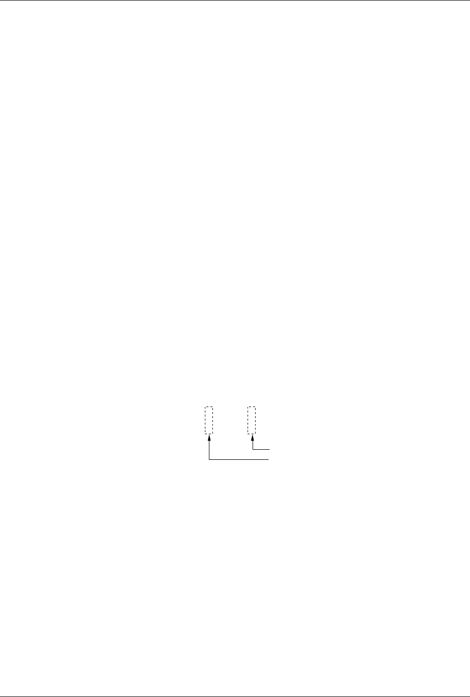
Figure 3-5
Illegal Bit Condition
1954-1
1111 1101
1011 1111
Device data (erased bit = 1)
RAM data to be programmed into the device
Illegal bit
Not an illegal bit
Tasks and Kits
ProMaster 2500 User Manual 3-9
•
Label
—Select this parameter to label the devices. Devices do not
have to be programmed (or verified) and labeled in the same process.
They can be programmed and placed in tubes to be labeled by the
2500 later. The 2500 default configuration will not label devices that
have failed the programming operation. (The 2500 can be configured
to label both passed and failed devices. Refer to the
Binning
command in local mode in Appendix F.) Devices that have failed can
be labeled only by passing them through the 2500 a second time.
Selecting Handling/
Labeling Parameters
Numerous parameters are available by selecting the
< More >
pushbutton. Press
↵
and the
More Task Parameters
selection box
appears (see Figure 3-1, screen 4). Most of these should remain at their
default settings.
The parameters that must be defined for all Tasks are the
Handling/
Labeling Parameters...
selections. Move the screen cursor over
Handling/Labeling Parameters...
and press
↵
to select this parameter
set. The following handler and labeler parameters are defined in this
dialog box.
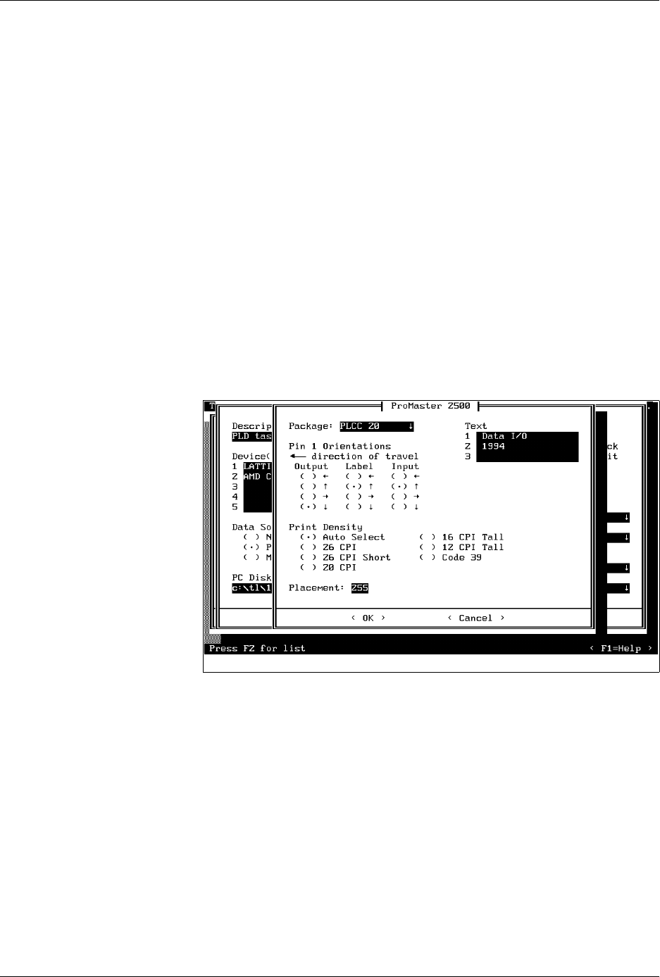
Selecting the Package Type
The
Package
field defines the device package type you will be
processing. Move the screen cursor to this field and press
F2
. TaskLink
displays a list of package and pin counts from 8-pin DIP to 84-pin PLCC
devices. The package type “
DIP 24-.3
” represents a 24-pin DIP device in a
300 mil. package width.
To select a new package type, move the screen cursor to the new type and
press
↵
.
Device Orientation: Pin 1
Press
T
AB
to move to the
Pin 1 Orientation
field. This parameter is
critical because it tells the 2500 where pin 1 on the device will be
positioned in the input track. The beam inserts the device into the
programming module with pin 1 always to the right, pointing toward the
input tube. The Task must accurately identify the position of pin 1 as the
devices are loaded in the input track so that the beam rotates and inserts
it in the programming module correctly.
Figure 3-6
ProMaster Dialog Box