2500_Users_Manual.pdf - 第330页
Wiring Dia gram C-4 ProMast er 25 00 User Man ual
Wiring Diagram
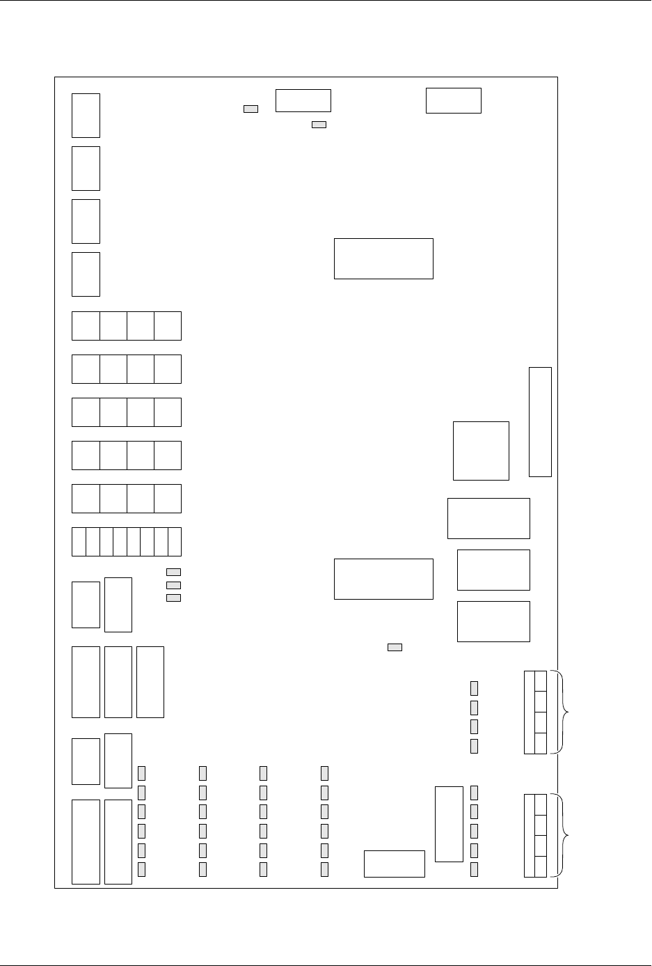
ProMaster 2500 User Manual C-3
Figure C-2
ProMaster 2500 Handler Controller Board Layout (not to scale)
26
25
24
23
22
21
20
19
18
17
ADC
Vac
ADC
Lbl
8
7
6
5
4
3
2
1
16
15
14
13
12
11
10
9
J9
Label
J10
Rotate
J12
In-tube
J13
Out-tube
J14
Display
J6
Programmer
J7
Encoder
J15
Keyboard
J5
Remote (Prog)
J3
5V, +/-12V
J4
Remote
J1
24V
J24 Solenoids
S8 S7 S6 S5
J25 Solenoids
S4 S2 S3 S1
1.
2.
3.
4.
5.
6.
7.
8.
9.
10.
11.
12.
13.
14.
Device out of input tube
Part detect
Beam down
Beam up
(Unused)
(Unused)
(Unused)
(Unused)
(Unused)
(Unused)
Device release, track 1
Device at output tube 1
Device release, track 2
Device at output tube 2
15.
16.
17.
18.
19.
20.
21.
22.
23.
24.
25.
26.
Input track motor CAL
Output track motor CAL
Beam reference position
Out of labels detect
Input tube detect
Output tube 1 detect
Output tube 2 detect
Front prog. module clamp
Rear prog. module clamp
Hood up
Main plate up (DMP)/
End of ribbon (TP)
Unused (DMP)/
Ribbon pinch
roller open (TP)
Optic Functions
U7
82530
U37
RAM
U16
EEPROM
U15
EPROM
12V 5V
-12V
U43
8751
EPROM
J2
36V
90V
J11
Beam
U14
80C188
CPU
J8
Test
J27
Thermal Print Head
37V
90V
CR
51
CR
87
CR
63
CR
99
CR
75
CR
111
CR
52
CR
88
CR
64
CR
100
CR
76
CR
112
CR
53
CR
89
CR
65
CR
101
CR
77
CR
113
CR
54
CR
90
CR
55
CR
102
CR
78
CR
114
S1
S2
S3
S4
Unused
Output track blower (LP)
Cut off (LP)
Beam up/down (LP)
S5
S6
S7
S8
Device blow off (LP)
High pressure (HP)
Vacuum (HP)
Prog. module clamp (HP)
24V S8 S7 S6 S5 S4 S2 S3 S1
2490-1
Dot Matirix Print Head LEDs
1
1
1
1
1
1
1
1
1
1111
1
1
1
111111
11
J22
Dot Matrix Print Head
J23
Dot Matrix Print Head
1
1
1
1
J15 J21 J17 J20 J16 J19
Notes
Pin 1 location for connector or IC
Dot matrix printer
Thermal printer
High pressure
Low pressure
1 =
DMP =
TP =
HP =
LP =
Refer to Figure 5-4 for specific connector pinout assignments
1
System Power
Serial Ports

Wiring Diagram
C-4 ProMaster 2500 User Manual

ProMaster 2500 User Manual D-1
D
Translation Formats
Translation formats are different ways of encoding the data in a data file.
A data file contains the information to be programmed into a device. The
data file could contain the fuse pattern and test vectors for a logic device
or the data for a memory device.
Generally, the data, such as the fuse pattern for a logic device, are created
on a development platform and are then stored in a particular data
translation format. When you want to transfer the data file to the
programmer, you will need to set up the programmer to handle the
correct translation format. During download, the programmer translates
the formatted data and stores them in user memory as a binary image file.