2500_Users_Manual.pdf - 第26页
Introduc tion 1-4 3/97 ProMa ste r 2500 User Ma nual Front Pan el — Th e front panel includes a n alphanum eric keyboard for text and data entry, and a 4-line, 160 -character back -lit display for communicatin g prompts …
Introduction
ProMaster 2500 User Manual 3/97 1-3
General Features
This section describes the major hardware components on the 2500. The
components are divided into three broad categories: external features,
features under the hood, and internal features.
Note: Illustrations in this manual show the ProMaster 2500 with an E-stop
button, hood interlock switch, labeler cover, and a modified hood with a
handle. Handlers with the dot matrix labeler installed do not have these
additional features.
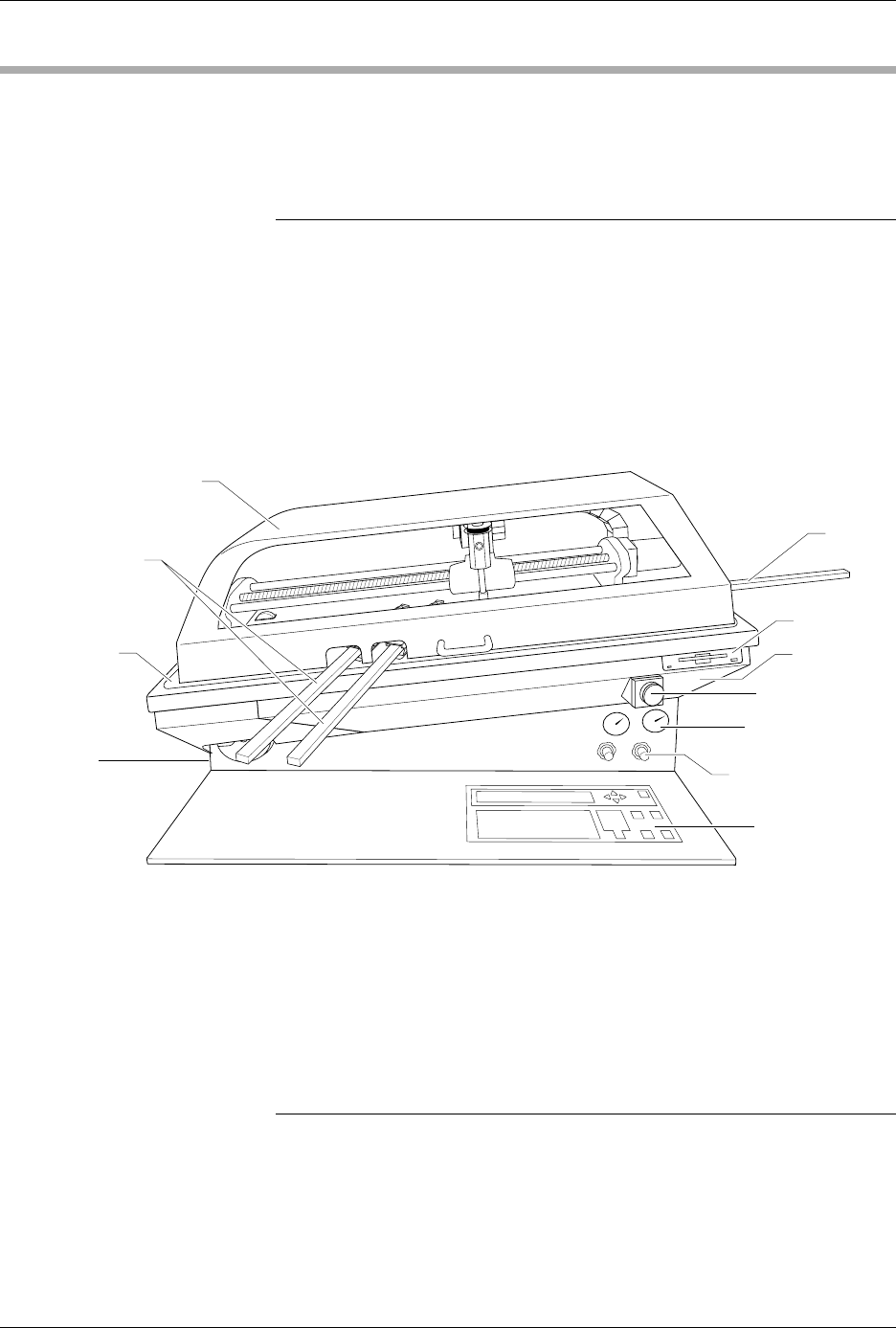
External Features
The primary external features of the ProMaster 2500 are identified in
Figure 1-2.
Front of 2500 Disk Drive
—The disk drive is used to update the Mass Storage Module
with operating system commands and programming algorithms used by
the programming electronics.
Hood
—The hood covers devices as the beam transports them through
the system. Figure 1-2 shows the hood in its operating position (down).
The 2500 will not operate (except when running diagnostics) while the
hood is raised.
Note: A safety interlock switch under the hood prevents the 2500 from operating
when the hood is up. The hood must be lowered to the operating position
(shown in Figure 1-2) before the 2500 will process devices. Service
personnel are provided with a key that is inserted into the switch keyhole
and turned to activate the switch. This allows them to service the handler
and run diagnostics when the hood is raised. If a user lifts the hood while a
Task is running, all handler motion will be stopped, but the power to the
handler will remain on.
Figure 1-2
External Features of the 2500
1749-3
OUTPUT TUBES
AIR PRESSURE
GAUGE
AIR PRESSURE
ADJUSTMENT KNOB
DISK DRIVE
BASE
INPUT
TUBE
MAIN PLATE
GROUND WRIST
STRAP CONNECTOR
(on the side)
FRONT PANEL
E-STOP BUTTON
HOOD

Introduction
1-4 3/97 ProMaster 2500 User Manual
Front Panel
—The front panel includes an alphanumeric keyboard for
text and data entry, and a 4-line, 160-character back-lit display for
communicating prompts to the operator. This panel is used primarily for
running diagnostics and invoking special handler/labeler firmware
commands. (Refer to page 1-11 for more detailed information.)
Output Tube Holders
—By default, the right tube holder (tube 1) accepts
all devices that have passed the programming/testing operation. The left
tube (tube 2) holds any devices that have not passed the system
programming and verify cycles.
Main Plate
—The primary surface on which the track, beam, and other
components described above are mounted. The system power supply and
controlling electronics boards are located in the base, under the main
plate. Two corner screws attach the hinged main plate to the base. With
these screws removed, the plate can be raised to allow access to service
the system electronics.
CAUTION: To prevent the main plate from accidentally falling shut, be
careful not to jar it when it is raised.
Ground Wrist Strap Connector
—The operator’s antistatic wrist strap is
inserted in this connector.
CAUTION: The devices being processed through the ProMaster 2500 and
components on the system’s circuit boards are static
sensitive and may be damaged by electrostatic discharge
(ESD). To help eliminate damage from ESD, operators and
service personnel should wear an antistatic wrist strap
while using the equipment. The wrist strap should be
connected to the grounding plug. It should contain a 1M ohm
(minimum value) to 10M ohm (maximum value) isolating
resistor.
Emergency Stop Button (E-stop)
—A red emergency stop button is
located below the disk drive on the right side of the front panel. Pressing
this button will shut off all input AC power to the 2500, immediately
stopping all handler movement and turning the programmer off. Devices
in the middle of the programming and labeling process (those in
programming module sockets and waiting in the middle track) will be in
an undefined state. All devices in the module sockets and tracks should
be removed from the 2500 and discarded. Power to the PC is not affected,
but TaskLink’s Job Status report statistics will not be accurate because the
information displayed on this screen includes devices that were in the
middle of the processing cycle when the power was turned off.
Remove all devices from the track sections and programming modules
before turning the power back on. To restore power, pull out on the red
E-stop button. The Task that was running when the button was pressed
must be restarted.
Air Pressure Adjustment Knobs
—High and low pressure can be
adjusted by using these knobs. High and low air pressure are used to
raise and lower the beam, pick up the device, assist devices into output
tubes, and clamp the programming module in place (see Figure 1-3).
Introduction
ProMaster 2500 User Manual 3/97 1-5
Back of 2500 AC Power Input and Power Switch
—The system is factory configured
to accept either 100/110 V or 220/240 V AC input. The input power
assembly includes the power switch and the input fuse for the system
(see Figure 1-4).
System Air Input
—Primary air input to the system. This is the source for
the high and low air pressure used by the pick-and-place beam. The air
input connector accepts a 1/4-inch plastic air line.
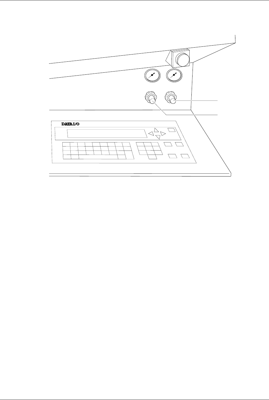
Figure 1-3
System Air Adjustment Knobs
LOW PRESSURE
20-50 PSI
HIGH PRESSURE
65-85 PSI
A
J
S
SHIFT
B
K
T
DEL
C
L
U
D
M
V
E
N
W
F
O
X
SHIFT
G
P
Y
H
Q
Z
I
R
ENTER
1
4
7
2
5
8
3
6
9
0
LOWER
CASE
RESET
STOP
CAL
START
ON
1764-4
HIGH PRESSURE
ADJUSTMENT KNOB
LOW PRESSURE
ADJUSTMENT KNOB