2500_Users_Manual.pdf - 第131页
Operation ProM aster 25 00 User Manua l 4-17 Replacing a Chuck T ip Remove the chuck from the bea m and remove the old tip. The new tip should extend sligh tly beyond the meta l end of the chuck so a n airtight seal can …
Operation
4-16 ProMaster 2500 User Manual
Removing and
Installing Chucks
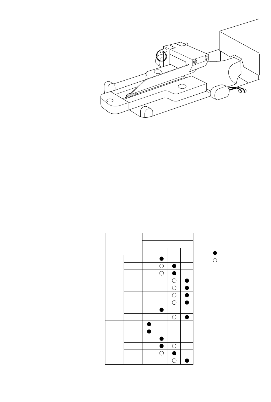
When you change to a new device package, select the appropriate chuck
as shown in the chuck selection chart (see Figure 4-13).
CAUTION: Chucks are released from the beam suddenly. If the beam is
positioned over the SPA pins or input track, the sudden
release may damage those areas.
Change the chuck with the beam directly over one of the two main plate
recesses. Keep the beam raised by holding it up with two fingers while
you use a downward pulling/twisting motion to remove the chuck. With
one hand on the beam for support, insert the new chuck by lifting it
straight up until it snaps into position.
Figure 4-12
8-pin 150-mil SOIC Device Keeper
Bar Assembly Mounted in the
Input Track
Figure 4-13
Chuck Selection Chart
2501-1
DEVICE
TYPE
PLCC
DIP
LMN
20-PIN
28-PIN
32-PIN
44-PIN
52-PIN
68-PIN
84-PIN
300 mil
600 mil
1850-3
Recommended
Alternate
SOIC 150 mil
220 mil
300 mil
330 mil
420 mil
500 mil
K
CHUCK
ProMaster 2500
Operation
ProMaster 2500 User Manual 4-17
Replacing a Chuck Tip
Remove the chuck from the beam and remove the old tip. The new tip
should extend slightly beyond the metal end of the chuck so an airtight
seal can be made. After it is on, lightly chalk the end of the tip before
processing devices. Chalking decreases the possibility of a device sticking
to the tip due to an accumulation of oils from being handled.
Adjusting High and
Low Air Pressure
Your external factory air input to the 2500 should be set so that it supplies
a constant 1.0 CFM at 80 PSI.
Note: To avoid unnecessary problems, be sure to provide the 2500 with a clean,
dry, externally filtered (10 micron) air supply.
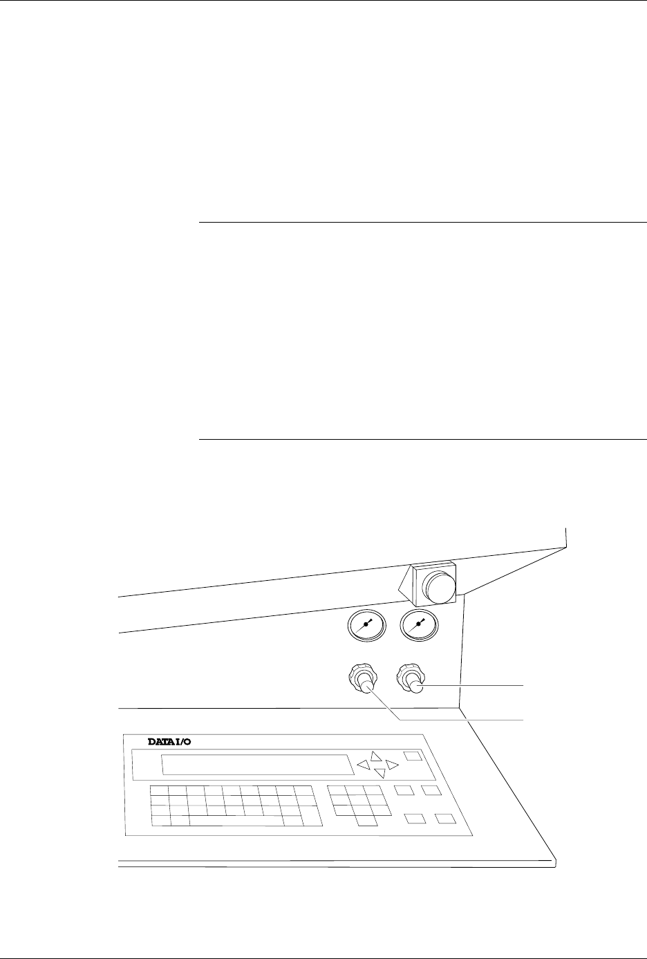
Adjust the high air pressure gauge on the 2500 to 75 PSI. When the
adjustment is correct, push the adjustment knob in toward the back of the
2500 to lock its position.
Set the low air pressure knob so that the gauge reads 30 PSI. It is normal
for this setting to fluctuate during operation, but it should not drop below
30 PSI or exceed 50 PSI. Make your final adjustments to the low pressure
setting after watching its fluctuation while the 2500 is processing devices.
See Figure 4-14. When the adjustment is correct, push the adjustment
knob in toward the back of the 2500 to lock its position.
Note: The ProMaster 2500’s high and low air pressure varies during operation;
this is normal and is not the symptom of a problem.
Figure 4-14
Adjusting High and Low Air Pressure
LOW PRESSURE
20-50 PSI
HIGH PRESSURE
65-85 PSI
A
J
S
SHIFT
B
K
T
DEL
C
L
U
D
M
V
E
N
W
F
O
X
SHIFT
G
P
Y
H
Q
Z
I
R
ENTER
1
4
7
2
5
8
3
6
9
0
LOWER
CASE
RESET
STOP
CAL
START
ON
1764-4
HIGH PRESSURE
ADJUSTMENT KNOB
LOW PRESSURE
ADJUSTMENT KNOB

Operation
4-18 ProMaster 2500 User Manual
Loading Labels
The 2500 labeler prints using either a 24-wire in-line dot matrix printer or
a thermal printer. Labels usually need to be changed each time a new
device package type or different pin count is required by the Task you are
going to run. Labels are positioned on a non-adhesive liner material so
they will peel easily as they advance around the label platen’s point. The
label part number and date code are written on a label attached to the
inside of the label roll.
Note: The label part number is marked on the inner cardboard reel. You can
identify a roll of ProMaster 2500 labels by the “QF” prefix in the part
number. Labels for other Data I/O products will look the same but cannot
be used on the 2500.
The 2500 allows you to adjust where the label is applied on the device.
This parameter, called label placement, will usually be changed by the
system administrator. To place the label, the 2500’s labeler must know
where the labels are on the liner and must be able to advance the liner so
the label contacts the device at the correct time. The label detection optic
assembly (known as the ADC optic) detects the leading edge of the label
so the label drive motor can position it for correct application to the
device.
If you are switching between Kapton™ and polyester labels, check the
ADC optic value (see page 5-34) and adjust it as required so that it reads
200
when reading the label on the liner. The ADC value changes slightly
for these two label material types.
Follow the instructions in the following sections for threading the new
label stock through the appropriate printer type’s assembly.
Loading Labels in the Dot
Matrix Printer
Rollers and other components of the labeler are referred to by letters in
this section to make the threading instructions easier to follow.
Refer to Figure 4-15 andthefollowingproceduretoinstallarolloflabels.
1. Raise the application plate and slide rollers
B
and
F
in the direction
shown by the arrows in Figure 4-15. This prepares the path of the
labels to be threaded through the labeler.
2. On a standard reel, the label release knob is attached to a core pin that
holds the label roll in place. Loosen the label release knob just enough
to move it toward the center of the reel (so that the core pin no longer
protrudes), and lock the knob in this retracted position.
For a magnetic supply reel, remove the plate.
3. If labels are already installed, unthread the liner, and remove the old
label roll by putting your thumbs in the cut-outs in the supply reel
and rocking the roll back and forth as you pull it off.
4. Install the labels on the supply reel so that the label liner passes to the
left of optic
A
(see Figure 4-15).
5. If the 2500 uses a standard reel, loosen the release knob and push the
pin into the cardboard core of the label roll. Tighten the knob to hold
the pin in place against the roll’s cardboard roll.
If the 2500 uses a magnetic supply reel, reinstall the plate.