2500_Users_Manual.pdf - 第145页
Operation ProM aster 25 00 User Manua l 4-31 4. Pr ess START . The beam rotates the device 90 ° and moves it over the programming m odule. Push the beam down manua lly (on either sid e of the beam limit bar), and ensure …
Operation
4-30 ProMaster 2500 User Manual
Check Front-to-back
Position
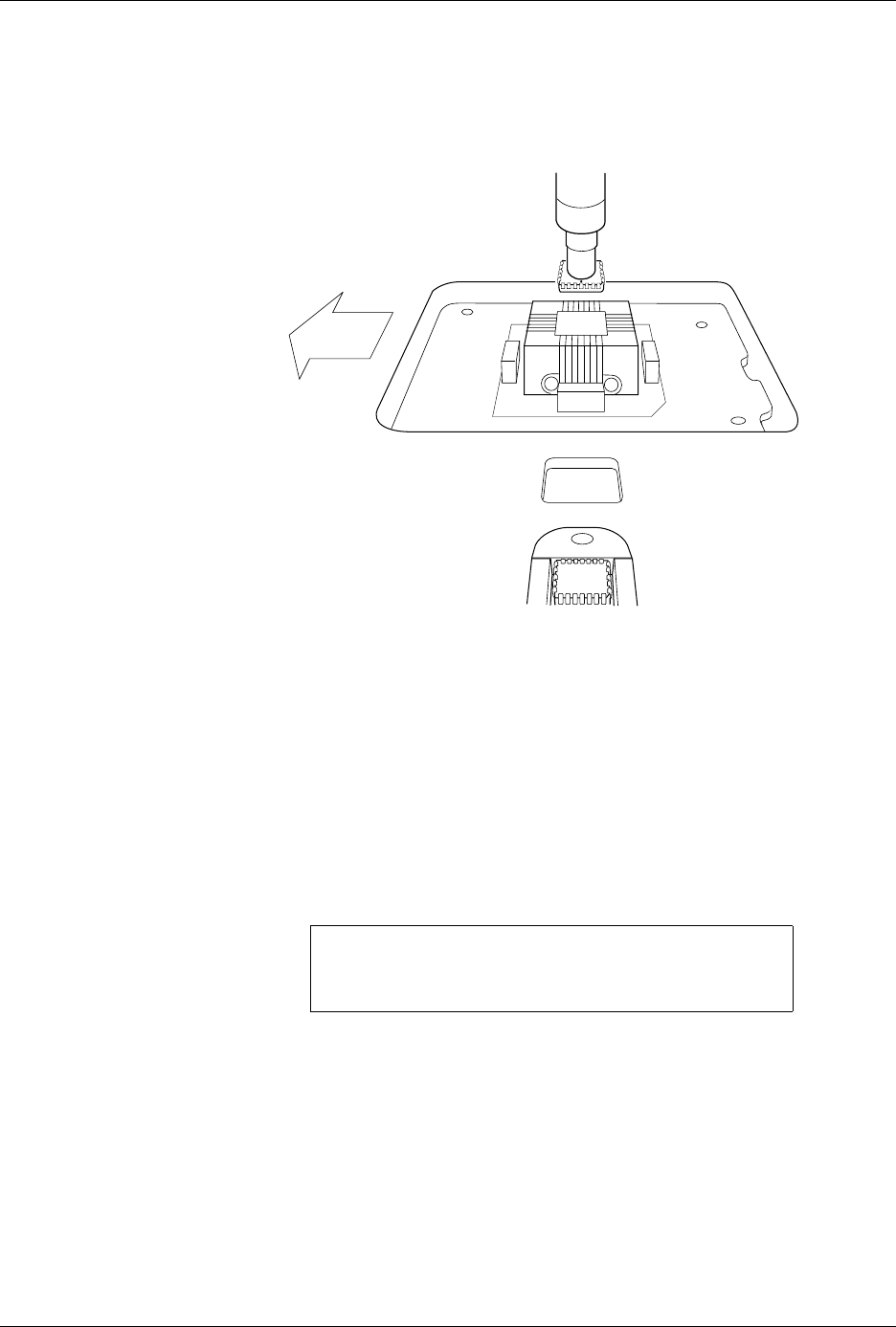
9. After the device is centered right-to-left, check its front-to-back
position by looking at the device and programming module from
over the input track.
10. If the device is centered over the programming module in the front-
to-back axis, press
START
to resume operation.
If the device is not centered front-to-back,
note
whether it is too close to
the
front
or
back
, and perform the following steps to readjust its position.
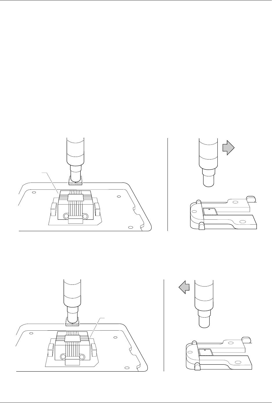
Adjust Front-to-back
Position
To realign the beam so that the device moves into the center of the
programming module on the front-to-back axis, follow the steps below.
1. Exit the Task or Kit, restart it, and prepare to recheck the alignment.
2. The beam will pause above the device and the 2500 displays:
3. If the device was
too close to the front
of the programming module,
press
→
once or twice so that the chuck picks up the device a little to
the
right
of its original position (see Figure 4-25). This is done to
compensate for the fact that the beam rotates the device 90
°
before
inserting it in the programming module’s block.
If the device was
too close to the back
of the programming module,
press
←
once or twice so that the chuck picks up the device a little to
the
left
of its original position (see Figure 4-26).
Figure 4-24
Checking the Front-to-Back
Alignment (looking from the
perspective of the input track)
PROGRAM/TEST ONLY
USE ARROW KEYS TO ALIGN BEAM WITH
DEVICE CENTER. PRESS [D] TO LOWER BEAM.
PRESS START TO CONTINUE.
1859-2
X
4
X1
X3
FRONT
OF 2500
Operation
ProMaster 2500 User Manual 4-31
4. Press
START
. The beam rotates the device 90
°
and moves it over the
programming module. Push the beam down manually (on either side
of the beam limit bar), and ensure that the device moves into the
center of the programming module’s block.
When the alignment is correct, press and hold
D
on the 2500
keyboard to check the device’s insertion.
Repeat steps 1 through 4 until the device moves into the center of the
programming module and does not rub one set of contacts more than
another.
5. When the alignment is correct, press
START
to continue running the
Task.
Figure 4-25
Device too Close to the Front
Figure 4-26
Device too Close to the Back
If the device was too close to the FRONT, move the beam to the RIGHT.
1860-2
X4
X1
X3
FRONT
If the device was too close to the BACK, move the beam to the LEFT.
1861-2
X4
X1
X3
BACK

Operation
4-32 ProMaster 2500 User Manual
Aligning a Device to a DIP/SOIC/32-pin PLCC
Programming Module
When you process a device with a rectangular shaped body (DIP, SOIC,
or 32-pin PLCC), the 2500 prompts you to align the first device in the job
run. Follow these steps to align the beam to a device in the input track.
The track width should be adjusted for the device before you begin this
procedure (see page 4-12).
Note: This alignment procedure assumes that the devices are inserted in the
input track with
pin 1 oriented to the right
when you are standing in
front of the 2500.
1. Insert a tube of devices into the input track and close the hood.
2. Start the new Task. The beam moves over the first device and pauses.
The 2500 displays:
3. Press
←
and
→
to center the chuck over the device (left-to-right).
Pressing the arrow key once moves the beam a small step in that
direction.
Note: You can change beam alignment while a Task is running. When the beam
hesitates above the device, press
STOP
and use the front panel arrow keys.
4. Press and hold
D
on the 2500’s keyboard to lower the beam and
check the position of the chuck on the device. For a slower insertion,
lower the beam manually by pushing directly on the top of the beam
assembly, on either side of the beam’s limit bar (the limit bar is shown
in Figure 1-7). Adjust the left-to-right position if necessary. When the
beam is centered, press
START
.
5. The beam picks up the device, moves it over the programming
module, and pauses before inserting the device. The 2500 displays:
6. Align the device pins to the module’s contacts using the
←
and
→
keys to move the beam with the device. The left-most pins of the
device should line up with the left-most contacts on the module.
Press and hold
D
key to lower the device into the programming
module and check the alignment.
Note: Do not press the arrow keys while the device is on the programming
module. Doing so may cause the beam to break its vacuum hold and drop
the device.
PROGRAM/TEST ONLY
USE ARROW KEYS TO ALIGN BEAM WITH
DEVICE CENTER. PRESS [D] TO LOWER BEAM.
PRESS START TO CONTINUE.
PROGRAM/TEST ONLY
USE ARROW KEYS TO ALIGN DEVICE WITH
PROG. MODULE. PRESS [D] TO LOWER BEAM.
PRESS START TO CONTINUE.