M20_Ope_E.pdf - 第115页
Chapter 2 Creating and Editing a Program 2-71 2-7-6-3 Block Data Conversion Menu: Program>DataEditUtilities>BlockDataConversion If the program contains block data (repeat data), the pr ogram data can be converted w…
Chapter 2 Creating and Editing a Program
2-70
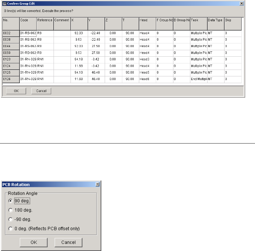
2-7-6-2 PCB Rotation
Menu: Program>DataEditUtilities>PCB_Rotation
This function allows you to create a new program with the coordinates for a rotated PCB by
modifying the coordinates in the original program.
Note: To perform this function, Board Size XY value in Board Data tab must be more than 0.
Window:
Rotation Angle When the X and Y values for "Board Origin" in the [Board Data] are not
"0", the offset value(s) will be added to the placement coordinates first,
and then the coordinates will be rotated (modified). When the PCB
rotation has been performed, the X and Y values will be "0".
When "0 deg. (Reflects PCB offset only)" is selected, only the offset
value(s) for the PCB will be reflected in the placement coordinates.
Note: To keep the original program, save the generated program after this function performed as
different file name.
Chapter 2 Creating and Editing a Program
2-71
2-7-6-3 Block Data Conversion
Menu: Program>DataEditUtilities>BlockDataConversion
If the program contains block data (repeat data), the program data can be converted with each
repeat offset value reflected on each placement coordinate.
However, the method for creating the original repeat data differs between that when all the panels
share the same origin and when each panel has its own origin.
Furthermore, if a mark step is present in the original repeat data, a mark group No. will be
assigned to each block when data conversion is performed.
Note: When the block data is converted and saved, the original block data will be lost. So, it is
recommended that the original block data be saved in another name and then block data
conversion be performed on that data.
Note: Block data conversion cannot be performed if the program is unsaved or contains data check
errors.
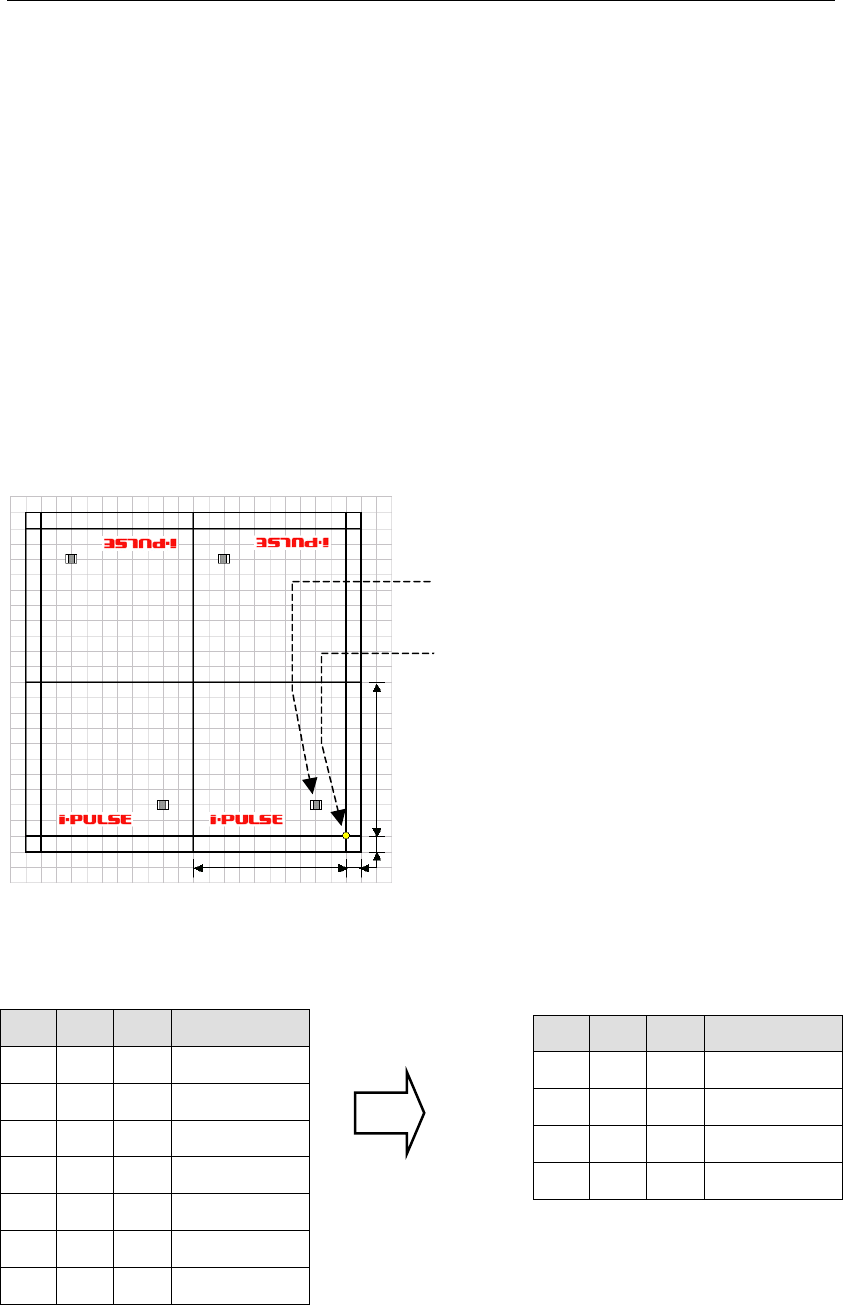
● Example 1 : When all the panels share the same origin (PCB origin X:10, Y:10)
100mm
100mm
10mm
10mm
Origin common to all
the panels
Placement coordinates
(
X:20, Y:20
)
X Y θ Task
Start Block
20 20 0 Single Pickup
End Block
100 0 0 Repeat Offset
100 200 180 Repeat Offset
200 200 180 Repeat Offset
X Y θ Task
20
20 0 Single Pickup
120
20 0 Single Pickup
80 180 180 Single Pickup
180
180 180 Single Pickup
Repeat data before conversion
Actual coordinates after conversion
Chapter 2 Creating and Editing a Program
2-72
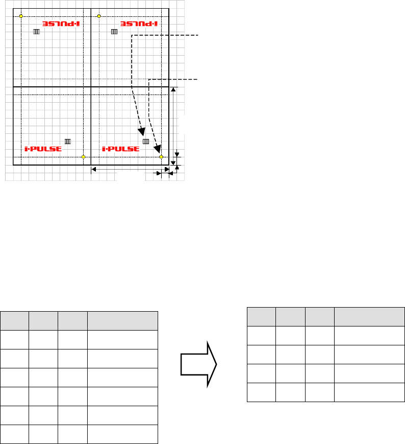
● Example 2 : When each panel has its own origin
100mm
10mm
100mm
10mm
Origin of each panel
Distance from panel’s origin(X:20,Y:20)
Note: Distance from PCB origin(X:30,Y:30)
Since only one PCB origin is specified, it is not possible to duplicate (repeat) data by rotating the
PCB whose origin has been offset. When each panel has own its origin as shown above, set the PCB
origin to X:0 and Y:0. As a result, the first component placement coordinates will be X:30, Y:30 in
the case of the above example.
PCB origin (X:0,Y:0)
X Y θ Task
Start Block
30 30 0 Single Pickup
End Block
100 0 0 Repeat Offset
100 200 180 Repeat Offset
200 200 180 Repeat Offset
X Y θ Task
30
30 0 Single Pickup
130
30 0 Single Pickup
70 170 180 Single Pickup
170
170 180 Single Pickup
Repeat data before conversion
Actual coordinates after conversion