M20_Ope_E.pdf - 第169页
Chapter 5 Libraries 5-19 Chip Capacitor Size Viewed by the Scan Camera Chip re sisto r Chip ca pacito r Vision-re cognized size Vision-re cognized size Reflec ted l ight does n’t fall u pon the came ra. Refle cted ligh…
Chapter 5 Libraries
5-18
Scan Camera Illumination for Chip Components (M6/M6ex/M6ez)
Determine the light value at which the nozzle is not captured. Set the value so that the entire
component gets even brightness. Use the front light of 0.
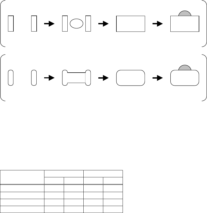
Lighting Method
Chip resistor view with only main light increased.
Only electrodes are
viewed.
Center of the body is
viewed.
The
entire
component is
viewed.
The nozzle is
viewed.
Chip capacitor view with only main light increased.
Only electrodes are
viewed.
Center of the body is
viewed.
The
entire
component is
viewed.
The nozzle is
viewed.
Adjust only the main light until the entire component gets even brightness. Make the half of the
value actual main light value. As even brightness for standard chip components is achieved at
the main light of 6, use the main light of 3. After the main light has been set, adjust the sub light
and measure the component using image test feature. Determine the sub light for correct size.
Set the sub light of about 10 for standard chip resistors. Use about 12 for standard chip
capacitors.
● Scan Camera Illumination for Resistors and Capacitors
Component Size
Resistor Capacitor
Main Sub Main
Sub
1005 3 10 3 12
1608 3 10 3 12
2125 3 10 3 12
3216 3 10 3 12
Chapter 5 Libraries
5-19
Chip Capacitor Size Viewed by the Scan Camera
Chip resisto
r
Chip capacito
r
Vision-recognized size Vision-recognized size
Reflected light doesn’t fall upon the
camera.
Reflected light fall upon the
camera.
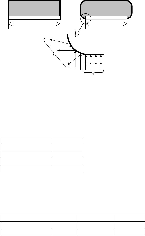
Chip capacitors, unlike chip resistors, have round corners to make the measured size smaller
than the actual one. In many cases, the apparent size of the component is 90% of the actual size.
Specify 90% of the actual size at "Overall X" and "Overall Y".
After specifying the size, be sure to execute the image test and make sure that the component
sizes displayed on the monitor are proper.
Example: (Unit: mm)
Actual component size Size setting
3.20 × 1.60 2.88 × 1.44
2.00 × 1.25 1.80 × 1.13
1.60 × 0.80 1.44 × 0.72
1.00 × 0.50 0.90 × 0.45
Melf Size Viewed by the Scan Camera
MELF components have cylindrical shape to make the measured size smaller than the actual
one. When using MELF nozzles, subtract 0.5mm from the actual component thickness.
Example: (Unit: mm)
Actual component size Thickness
Size setting Thickness
1.40 × φ3.5diam.
3.5
1.40 ×3.15diam.
3.0
2.00 × φ6.0diam.
6.0
2.00 ×5.40diam.
5.5
Notes on Using the Scan Camera Illumination
If the lustrous mold gives white reflection in some components with plastic mold, set the main
lighting at 2 or less. If such components can not be processed successfully using the scan
camera, use a fixed camera.
Note: If any dust or dirt is sticking to the surface of the mirror of the indirect scan camera, the
captured image may become dark.
Unlike the household mirror, the surface of this mirror is very vulnerable to scratch. So, be sure
to use a blower brush to clean the mirror.

Chapter 5 Libraries
5-20
■ Fixed Camera Illumination (M6)
Three kinds of illumination are available for fixed cameras: “Coaxial”, “Diffused” and “Side”.
“Coaxial” acts as direct light, “Diffused” as diffused light and “Side” as sideways slit light.
Normally, these three illuminations are used together to provide diffused light consisting of
light from various directions. For BGA and CSP components, only “Side” must be used.
■ Fixed Camera Illumination (M6ex/M6ez)
Three kinds of illumination are available for fixed cameras: “In”, “Out” and “Side”. “In” acts as
direct light, “Out” as diffused light and “Side” as sideways slit light.
Normally, these three illuminations are used together to provide diffused light consisting of
light from various directions. For BGA and CSP components, only “Side” must be used.
■ Beam Camera Illumination (M7)
Three kinds of illumination are available for beam cameras: “Coaxial”, “Diffused” and “Side”.
“Coaxial” acts as direct light, “Diffused” acts as diffused light, and “Side” acts as sideways slit
light.
For standard components, use “Diffused” as major light and “Coaxial” as subsidiary light.
Normally, use “Coaxial” and “Diffused”. (recommended to set the same value for both.)
For components with J-leads(SOJ and PLCC etc.), these three illuminations are used together to
provide diffused light consisting of light from various directions. For BGA and CSP
components, only “Side” must be used.
● Beam camera illumination settings for registers and capacitors
E.g.)
Component Size
Resistor Capacitor
Coaxial Diffused
1005 6 10
1608 6 10
2125 6 10
3126 6 10
■ Teach Camera Illumination
Two kinds of illumination are available for teach cameras: “In” and “Out”. “In” acts as direct
light and “Out” dose as diagonal diffused light.
● “Gain” and “Offset” for Fiducial mark and Bad mark
An original image outputted by a camera is processed for better and stable one by adjusting
“Gain” and “Offset” value.
Increasing “Gain” value clears the contrast and increasing “Offset” value intensifies the entire
brightness.
Specify the value in “Gain”/”Offset” for fiducial mark and bad mark. Increase “Gain” value to
clear the contrast and decrease the “Offset” value for fine adjustments.
Scanning Direction
Teach cameras look downward. Scan cameras, fixed cameras and beam cameras look upward.
The operator, when watching components and a board in the machine, looks downward. The
operator and the teach camera face in the same direction, however scan cameras, fixed cameras
and beam cameras in the opposite direction to provide a mirror image.