M20_Ope_E.pdf - 第318页
Chapter 10 Replenishing Com ponents and Using Maintenance Menus 10-14 ■ Motor ■ Motor sensor Window: ALM: Alarm MEL: Minus End Lim ited PEL: Plus End Limited MARK: Mark INP: In Position MSLD: Minus Slow Down PSLD: Plus S…
Chapter 10 Replenishing Components and Using Maintenance Menus
10-13
10-4 Signal I/O
Signal I/O stands for signal input/output. Signal input refers to an input signal sent from each
sensor. Signal output refers to an output command sent to each actuator.
The Signal Output (Control) window serves as controls to move actuators for checking their
movements. In response to their movements, the Signal Input (Monitor) window shows the
positions of motors and actuators and the sensor On/Off status.
10-4-1 Signal Input Monitor
You can check the current status (On/Off) of each sensor. “1” indicates on, “0” off. When a
sensor detects the movement of a switch, motor, or actuator, the Signal Input Monitor shows the
sensor status change. This is also used to find a wire disconnection or sensor failure.
Menu: Menu: Manual>Signal I/O>Signal Input (Monitor)
■ List ………. Not used
■ Details…… Not used
■ FIO……….. Not used
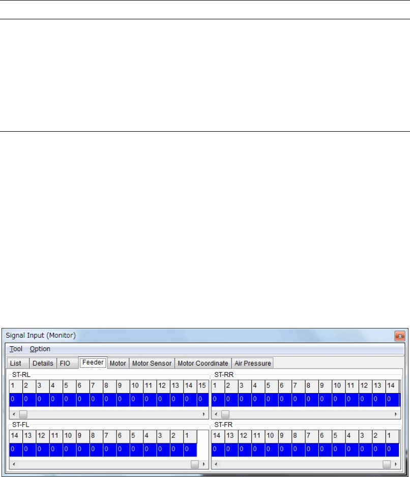
■ Feeder
“1” indicates no feeder is set.
“0” indicates a feeder is set.
The upper part is the signal input monitor for the front feeder bank.
The lower part is the signal input monitor for the rear feeder bank.
Chapter 10 Replenishing Components and Using Maintenance Menus
10-14
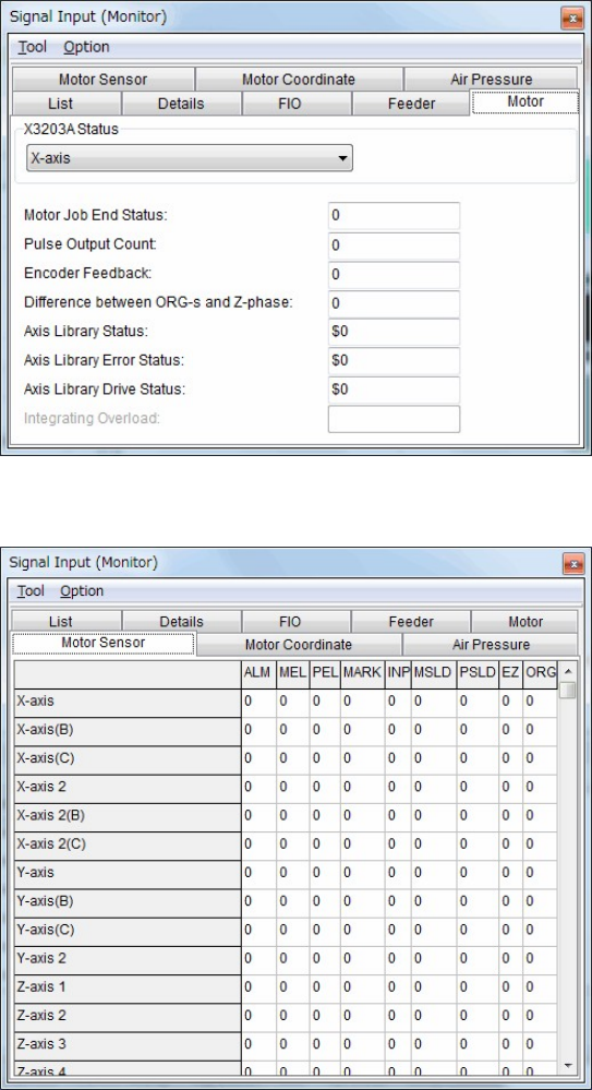
■ Motor
■ Motor sensor
Window:
ALM: Alarm
MEL: Minus End Limited
PEL: Plus End Limited
MARK: Mark
INP: In Position
MSLD: Minus Slow Down
PSLD: Plus Slow Down
EZ: 0 Phase
ORG: Origin
Chapter 10 Replenishing Components and Using Maintenance Menus
10-15
10-4-2 Signal Output Control
The Signal Output (Control) window serves as controls to turn on or off actuators. “1” indicates
On state, “0” Off state. “0” and “1” toggle as you click on it, and the corresponding actuator is
turned on or off simultaneously. This operation allows you to check actuator movement in
troubleshooting. When an actuator moves properly by this operation, its sensor responds and
the Signal Input (Monitor) window shows the result. The combination of an address and bit
number (0-7) represents a signal. The name of each signal is shown in the Details tab.
Turning on/off signal output in the Signal Output (Control) window allows an actuator
to move. During this operation, do not stick your head, hands, or other parts of the body
inside the mounter or tray feeder. Serious injury can result. Also make sure
non-operators are a safe distance from the mounter or tray feeder.
During signal output on/off operation, make sure no foreign obstacles are left in the mounter or
tray feeder. Otherwise, costly machine damage can occur.
Menu: Manual>Signal I/O>Signal Output (Control)
■ List ……… Not used
■ Details ….. Not used
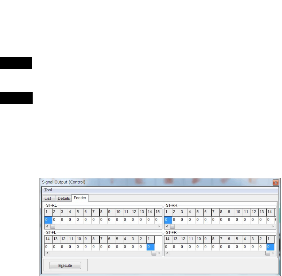
■ Feeder
This tab allows you to operate the part feeders set in the front and rear feeder banks.
Action:
① Scroll left or right to display the desired feeder number.
② Click “0” of the desired feeder number to switch it to “1”.
③ Click <Execute> button to allow the feeder to move for one feeder indexing.
Warning
Caution