M20_Ope_E.pdf - 第178页
Chapter 5 Libraries 5-28 5-1-2-5 Illumination Adjustment The illumination adjustment tool supports the crea tion of illumination settings to be used for image processing. It measures combinations of “main and sub” or “Co…
Chapter 5 Libraries
5-27
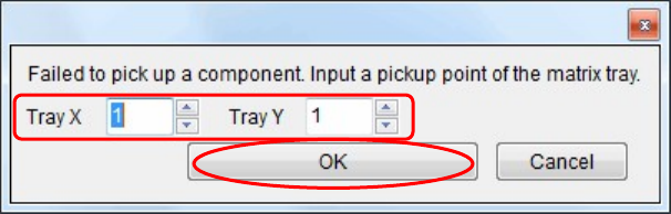
④ Additionally, if it is failed to pick up the component from the tray, the following window
will appear.
Change the pickup point of the matrix, and then click <OK>.
The pickup point is then changed to pick up the component again.
⑤ The image data window corresponding to the component will appear.
⑥ When the image test is completed and the image data window is closed, the component is
rejected or reused according to the [Reject/ Reuse] setting of the pickup data.
Additionally, the pallet is returned to the tray feeder.

Chapter 5 Libraries
5-28
5-1-2-5 Illumination Adjustment
The illumination adjustment tool supports the creation of illumination settings to be used for
image processing. It measures combinations of “main and sub” or “Coaxial and Diffused”
illuminations automatically and then allows the operator to select the most suitable setting.
This tool supports the processing of all the components and fiducial marks. This section
explains how to create component image data.
■ Illumination Adjustment Procedure
① Open the image data edit window for the target component. (Correct component
thickness must be entered.) Select Prearrange > [Set Default] / [Pick& Reject] and enter
the pickup-point (ST No.) to pickup the component with an appropriate nozzle.
② When creating new image data, first execute ADA to create temporary image data.
(Correct component thickness must be entered.)
Note: In the case of components not supported by ADA, necessary information must be entered
manually to create temporary image data.
Note: The illumination adjustment tool measures illumination settings in such a way that the size of
the target component can be recognized accurately. So accurate component size and lead width
must be entered in the image data.
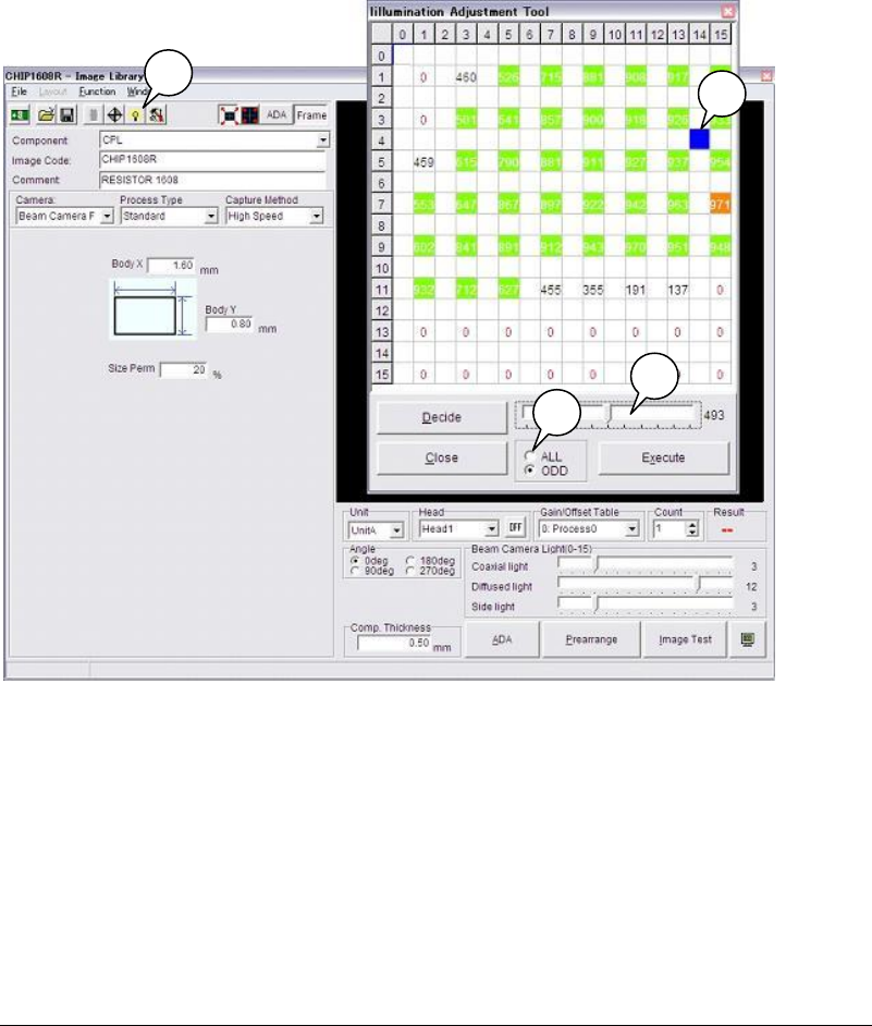
③ Click [Illumination adjustment tool] button (indicated by “A”) in the image data edit
window.
④ The [Illumination adjustment tool] window appears, so select “ALL” to measure all the
combinations (256 combinations) or “ODD” to omit some measurements (64
combinations). (Indicated by “B”)
Note: Numbers “0” to “15” given on the vertical and horizontal lines indicate “main and sub” or
“Coaxial and Diffused” illumination settings (in 16 steps), respectively.
⑤ Click [Execute] button. A message “Execute searching for the proper Illumination?”
appears, so click <OK> to start measurement.
⑥ When measurement is complete, results will be displayed. (The results shown below are
when ODD is selected.)
Green cells indicate the illumination settings that are judged to be appropriate, and
orange cells indicate the setting with the maximum sore.
Note: If measurement is performed with “ODD” selected, some cells will be empty since some
combinations are omitted.
However, if the results in empty cells are within the appropriate illumination setting range,
they can also be used. (Example: blue cell indicated by “C”)
Chapter 5 Libraries
5-29
⑦ The score’s threshold value is entered automatically based on the measurement results.
(Indicated by “D”) This can be changed freely. For instance, if you want to narrow down
the measurement results, drag the threshold slide bar to the right (to higher score). Only
the higher score combinations will be displayed in color (in this example, combinations of
score 493 or higher will be displayed in color, since the threshold value is 493).
⑧ Click an appropriate illumination setting and then click <Decide>. The “main and sub” or
“Coaxial and Diffused” illumination will be set automatically.
⑨ Execute the image test, and check that the Vision window does not show any reflection of
the nozzles and a clear image of the component is displayed.
⑩ If you want to change the illumination settings, repeat steps ⑧ and ⑨.
Note: For the gain and offset, the initial values of the image data will be used. (“0” for chip
components, and “10” for leaded components such as ICs)
To change the gain/offset values, change them manually and then re-execute measurement.
5-1-2-6 ADA
ADA acquires various data required for image processing by measuring the component
automatically, and creates image data. Conventionally, component dimensions have to be
measured using calipers to enter image data. This is an inefficient method since it consumes a
lot of labor and time. Use of ADA reduces both labor and time, enabling efficient data creation.
■ Target Component Codes
Image codes for Chip, Transistor, Power transistor, SOP, SOJ, PLCC, LCC, QFP and BGA/CSP
(except white substrate BGA/CSP) components are supported. Four Terminal Search, Blob
process, CPL process and BGA and Connector are not supported.
A
B
C
D