M20_Ope_E.pdf - 第223页
Chapter 5 Libraries 5-73 Settings for BGA/CSP mode (Im ageLibrary>SelectComponent>BGA/CSP) As for Ball Pitch, Ball Size, Ball Count X, Ball Co unt Y, click on each setting field and see the graphical description …
Chapter 5 Libraries
5-72
When the Component setting is either:
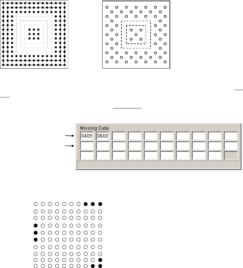
4: Partial grid, matrix
5: Partial grid, staggered
First, assign the area to skip the ball check process. Squares are numbered from the outermost
one (1st square, 2nd square...).
In the above left BGA, 4th, 5th, and 6th squares are devoid of balls. Enter their numbers (04, 05,
and 06) as shown below. Up to two square positions can be set to a field. Be sure to use the top
line for this setting. (For the above right BGA, enter “0405” to the first field.)
Second, enter the missing ball setting to the second line
following the procedure for the
Component settings: 0, 1, 2, or 3.
Note: BGA with three or more sequential missing balls in the outermost ball square may not be
vision-processed properly.
Example 1
Example 2
Example 3
Vacant squares
Missing balls

Chapter 5 Libraries
5-73
Settings for BGA/CSP mode (ImageLibrary>SelectComponent>BGA/CSP)
As for Ball Pitch, Ball Size, Ball Count X, Ball Count Y, click on each setting field and see the
graphical description displayed in the sub-windows.
z Ball Alignment
Click <Mode> button to select a ball alignment pattern.
Note: When your BGA/CSP substrate is made of ceramic, select [White susbtrate BGA] from
BGA/CSP type. White substrate BGA/CSP is only available on the M6.
0
1
Note: A BGA/CSP must have munimum of 4 balls up to 64 balls per outermost ball row to be
handled. Also balls in a row must be sequentially aligned, with no irregularly skipped balls.
However, even when these limitations are met, some components with unique ball pattern (see
the below example.) cannot be processed. In such a case, consult us.
Example: The following ball pattern of RDRAM can be processed:
z Perimeter Grid
Enter the outermost square number of the lacked-ball perimeter. For both examples shown
below, the setting shall be “4”.
z Partial Grid
Enter the innermost square number of the lacked- ball perimiter. For both examples shown
below, the setting shall be “4”.
Note: To enable the Partial Grid setting, enter other than “0” for Perimeter Grid.
2
3
Matrix Staggered
XY Dif Pitch Matrix
XY Dif Pitch Staggered
Chapter 5 Libraries
5-74
Note: To enable the Perimiter Grid setting, enter the bigger value than its value for Partial Grid until
the inner ball grids disappear.
Note: Instead of using Perimeter Grid setting and Partial Grid setting, you can specify the lack of ball
position by “Rondom Ball Arrangement” function that is described later.
z Ball Pitch Perm.
An error occurs when the measured ball pitch is out of the range of,
Specified ball pitch +/- Ball pitch permission.
Larger the value, less severe the requirement will be.
When
Measured ball pitch < Specified ball pitch - Ball pitch permission,
or
Measured ball pitch > Specified ball pitch + Ball pitch permission,
an error occurs.
Unit: mm, Standard: 0.2
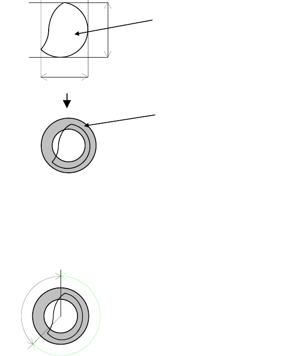
z Ball Circum. Perm.
Check is made on how much the ball circumference measured in the process of [Ball Check]
>Presence&Damage is in the circumference permission range determined from actually
measured ball size. Larger the value, less severe the requirement will be.
Unit: %, Standard: 40
Circumference
Actual measured ball size=(A+B)/2
Circumference permission range
This permission is determined in percent. Even if the ball is proper, the circumference may be
slightly out of the range.
Example: Improper ball:
The circumference is about 45% out of the range. When the setting is 40, the error mark is
displayed.
OK
NG
Circumference permission = NG/(OK+NG)
z Ball Size Perm.
An error occurs when the measured ball size is out of the range of the Ball Size Permission in
the process of [Ball Check]>Presence&Damage. Larger the value, less strict the requirement
will be.
Unit: %, Standard: 40