M20_Ope_E.pdf - 第300页
Chapter 9 Running a Job 9-28 ⑤ When the ma rk code is input in the [Image Co de for Feeder Suppfort] of the pickup data, XY offsets of the pickup point can be acquired by the image test. ⑥ Click the <Teach Coordinates…
Chapter 9 Running a Job
9-27
9-5-5-2 Edit & Teach during a Job Run (ST-F/ST-R)
Action:
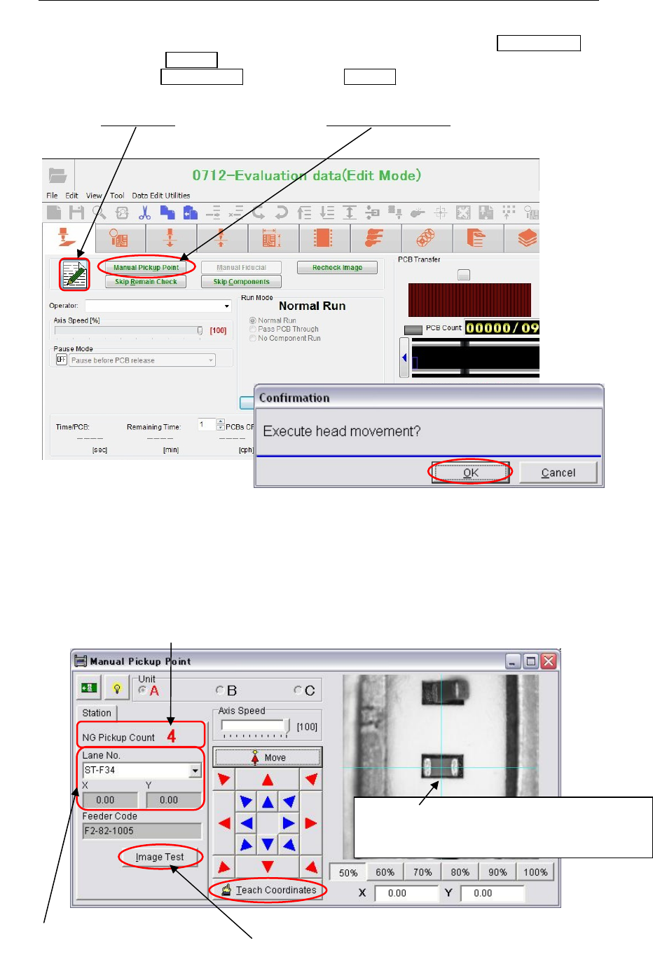
① If the mounter stops due to pickup error during a job run, first press the ALARM OFF
switch (and the CLEAR
switch) to stop the alarm.
Then press the RECOVERY
switch (and the CLEAR switch again) to recover from the
error.
② The [Edit&Teach]
button appears and the <Manual Pickup Point> button becomes
available.
③ When the mounter recovers from the error, the head travel message appears. Click the
<OK> button to move the main teach camera to the pickup point where the pickup error
occurred.
④ When the main teach camera reaches the pickup point, the following teach window
appears. Teach the center of the pickup point. Click the <Teach Coordinates> button to
determine the coordinates.
The number of pickup points error happened.
In the field, the lane No. pickup error
occurred appears. Also the YX offset
values of its pickup data appear.
When the mark code is input in the [Image Code for
Feeder Support] column of the pickup data, image
test can be executed to acquire its XY offsets.
A guide window appears at the pickup point.
When component dimensions are more than
5mm, a guide window changes to cross-hairs.

Chapter 9 Running a Job
9-28
⑤ When the mark code is input in the [Image Code for Feeder Suppfort] of the pickup data,
XY offsets of the pickup point can be acquired by the image test.
⑥ Click the <Teach Coordinates> button. The confirmation message appears. Click the
<OK> button.
⑦ If errors occur at more than one pickup point, repeat steps ③ to ⑤ for all the pickup
points which had errors.
Repeat the following procedures.
- Move the main teach camera to the pickup point.
- Teach the center of the pickup point.
- Determine the coordinates.
⑧ When all the pickup points are manually corrected, close the teach window. The
following confirmation message appears. Click the <Yes> button to save the changes.
⑨ To close the [Edit&Teach] mode, click the [Edit&Teach] button.
⑩ Press the START
switch to restart the job run.
Note: When the [Comp. Exhaustion Automatic Release] is disabled in System > User Parameter >
Functions(1), change the [Feeder Skip] data from “1” (disable) to “0” (enable) of the
Component Count column in the run window. Then press the START
switch to restart the
job run.
Chapter 9 Running a Job
9-29
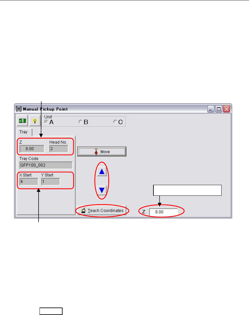
9-5-5-3 Edit & Teach during a Job Run (Tray Feeder)
Action:
① When a pick up error happened on the tray feeder, a head travel confirmation message
appears. Click the <OK> button to move the same head to the tray pocket where the
pickup error happened.
② The following teach window appears. Teach the component surface with arrow keys.
Move the head down slowly by observing the clearance between the nozzle tip and the
component surface. While moving the head down, the head height coordinate is indicated
in the [Z] field.
Note: Do not move down the head quickly or the attached nozzle, the head, and the component may
cause damage. When the nozzle tip almost reaches the component surface, move down the
head approx. 1mm more for reliable pickup.
③ When the height is determined, click the <Teach Coordinates> button.
④ The procedures hereafter is same as for ST-F/ST-R described in the prior section.
Change the component height in the tray data and save the change.
⑤ Press the START
switch to restart the job run.
Note: If still pickup error happens, try to lower the component height approx. 0.1mm more.
Component height entered in the tray data and
the head No. which had
p
icku
p
error a
pp
ears.
The position of tray pocket where
the pickup error happened.
Head height coordinate