M20_Ope_E.pdf - 第227页
Chapter 5 Libraries 5-77 Comparison between BGA mode and BGA/CSP m ode BGA mode Upper-right Ball Coordinate Lower-left Ball Coordinate Ball-less Square (Missing Data) Full grid -- -- Not required Perimeter grid Require…
Chapter 5 Libraries
5-76
② The component is displayed graphically (white
indicates existing balls, black indicates non-existing
balls). Balls switch from white to black and vice versa
alternately each time they are clicked.
④Selecting here enables you to change the
graphic size using the scroll bar.
⑤Clicking <Initialise> button restores the
original ball arrangement (i.e. all the balls
including unnecessary ones are present).
z Random Ball Arrangement
Menu: ImageLibrary>View
Action: To specify the random ball arrangement for BGA/CSP components, execute the following
steps.
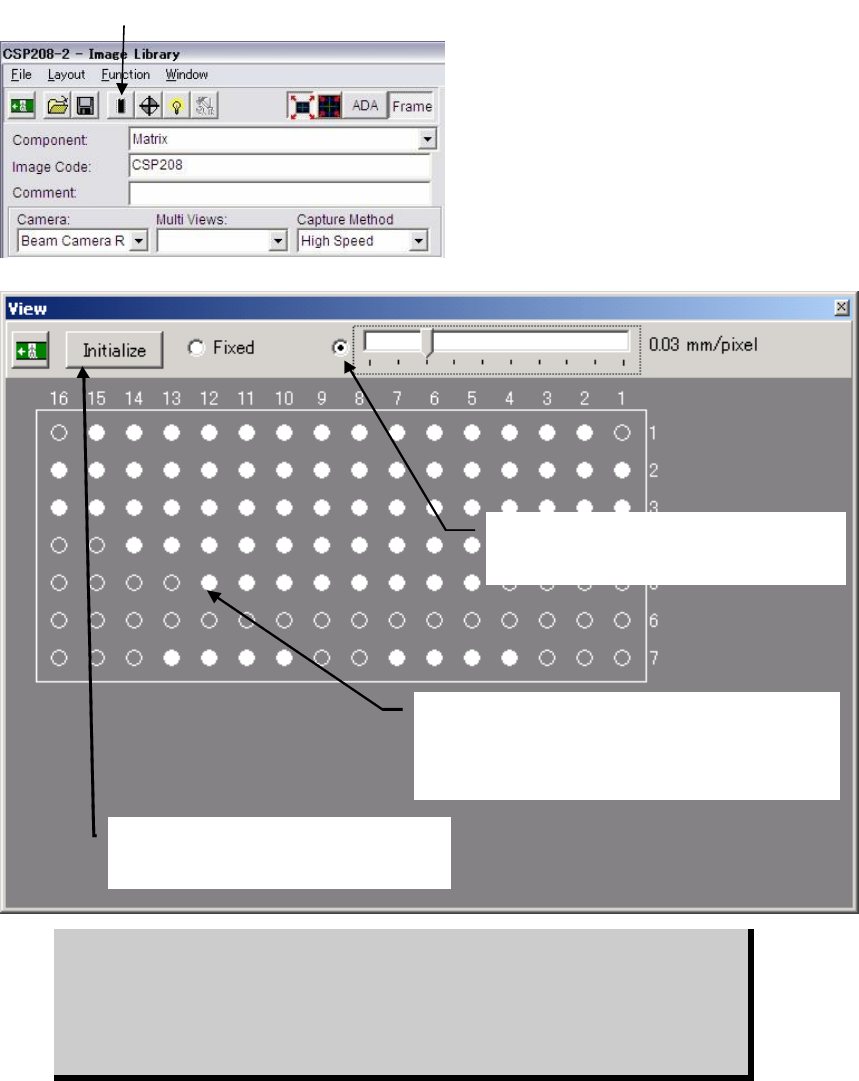
① Click <View> button in the image data edit window to open the View window.
② The component is displayed graphically with all balls present, according to the X/Y ball
count, ball size, ball pitch specified in the image data edit window.
③ Click unnecessary balls (i.e. balls that do not exist on the actual component) with the
mouse. They will turn from white to black. Black balls will be ignored during image
processing, so make sure that unnecessary balls are clicked to provide the actual ball
arrangement.
④ If the graphic display size is too large or too small, slide the scroll bar to reduce or enlarge
the size.
⑤ To restore the original ball arrangement (i.e. all the balls including unnecessary ones are
present), click <View> button.
BGAs can be handled either via the BGA mode or the BGA/CSP mode. But we
recommend you to use the BGA/CSP mode for the following reasons. When
using the BGA/CSP mode, missing balls assignment can be easily performed
by using the ball numbering system used in the component catalog. Also the
limitations stated on page 5-72, Note, won’t occur when the BGA/CSP mode is
used.
① Click the <View> button.
Chapter 5 Libraries
5-77
Comparison between BGA mode and BGA/CSP mode
BGA mode
Upper-right Ball
Coordinate
Lower-left Ball
Coordinate
Ball-less Square
(Missing Data)
Full grid -- -- Not required
Perimeter grid Required Required Not required
Partial grid -- -- Required
BGA / CSP mode
Perimeter grid Partial grid Random ball
Full grid Not required Not required Not required
Perimeter grid Required Not required Not required
Partial grid Required Required Not required
Random ball Not required Not required Required
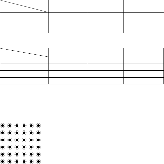
Illuminator Settings
Increased quantity of the side light results in brighter side portion and then center portion.
Adjust the quantity so that the center of a ball is slightly dark.
Note: Do not use the outside light.
Note: The best way: Prepare a ball-missing BGA component. Adjust illuminator settings so that the
image of normal balls can be clearly captured, while ball-missing portion is unseen.
Ball Pattern
Setting
Ball Pattern
Setting
Chapter 5 Libraries
5-78
5-1-5-13 Fiducial Marks
Register the fiducial model for the fiducial image data using a sample board from the
production lot. This model will be the reference to be compared with the actual fiducial on each
board. The fiducial process allows the system to measure and compensate X/Y/T offsets and
stretch/shrink of the board pattern to achieve precise placement for the overall program.
Fiducial Process
There are two ways to perform the fiducial process:
1. Pattern matching
This process allows for comparison between the registered fiducial model and an actual
fiducial on a board to see the offset between them. Its capability is hardly susceptible to the
inconsistent lightness of the overall or part of the fiducial image, or to the unclear fiducial
image due to its unsmooth surface. It is recommended that this process should be selected.
2. Center search based on fiducial shape
This process does not require time-consuming model registration unlike the pattern matching.
It merely requires you to select a fiducial shape to perform fiducial center search.
z Fiducial Mark Centering
The coordinates of the center of the fiducial model must correspond to the programmed
fiducial coordinates. If the fiducial model is registered off-centered, the offset value is added to
the compensation value to result in mis-compensation for all the production lot. To prevent this,
in teaching the fiducial model, the Model centering allows a fiducial to be centered
automatically by the vision process system, not manually, for proper registration. Before this
feature can be used, the fiducial shape and size must be specified.
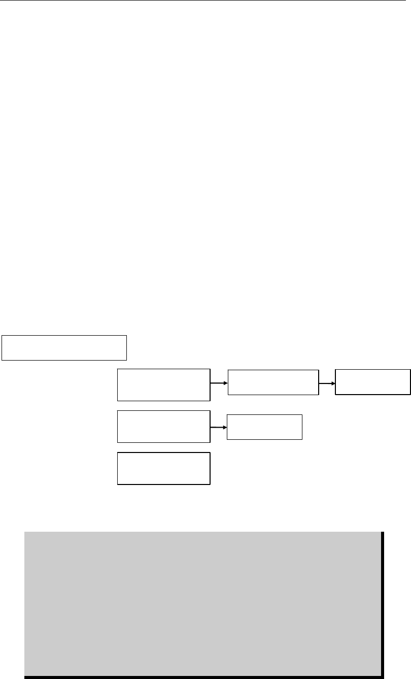
Summary of processing
Center search by
specifying shape
Pattern matching
(Actual model)
Model centering
Acquire model
Pattern matching
(Template model)
Register shape and
dimensions.
Register shape and
dimensions.
Register shape and
dimensions.
Acquire model
The “Actual model” for fiducial ‘Pattern matching process’ is registered actually
captured by the teach camera.
On the contrary, “Template model” for fiducial ‘Pattern matching process’ is
created from the specified mark shape and input sizes. “Template model” is
recommended to use for the fiducial pattern matching process because;
① The “Template model” does not require model centering and an accurate
mark model can be created.
② Besides, illumination setting of “Template model” can be adjusted by Image
Test even after model registration to get a better result of “Actual score”.
③ Only common mark shapes; circle, square, diamond, and triangle, are
available for “Template model”.
④ Use “Actual model” for the rest of mark shapes.