M20_Ope_E.pdf - 第204页
Chapter 5 Libraries 5-54 5-1-5-5 Multiple-view Process Usually, the component image is captured as a whole picture. But when the comp onent is too large for the camera view, it can be captured se parate pictures. In mult…
Chapter 5 Libraries
5-53
5-1-5-4 Camera Assignment
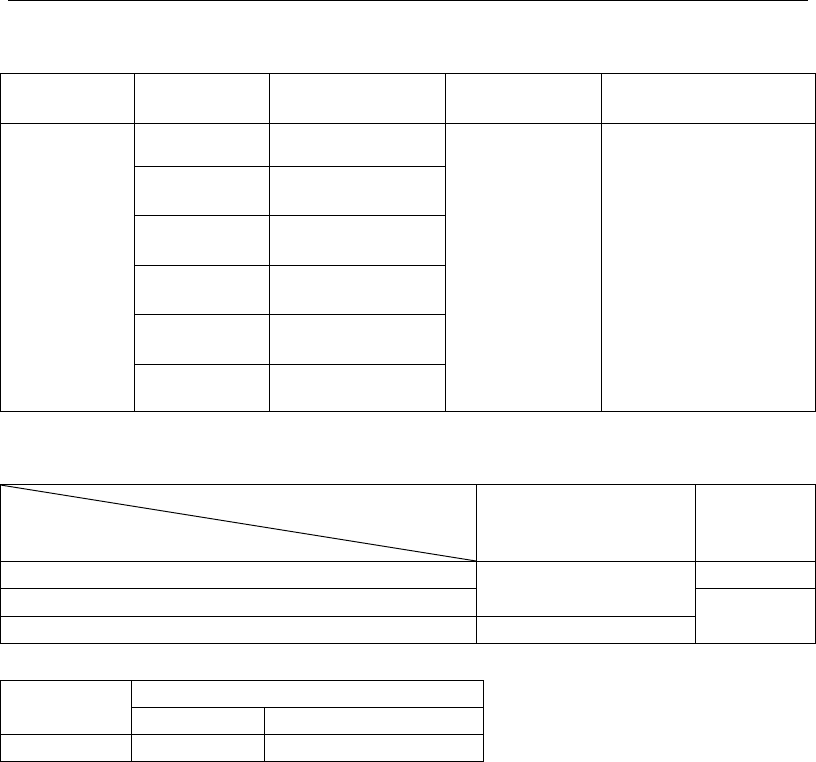
Refer to the camera specs. shown below for assigning an appropriate camera for the
component (use for image test and ADA).
Camera type
Vision
process
Applicable max.
component size
Applicable min.
lead pitch
Applicable min. ball
diameter/ball pitch
Multi-Scan
Camera
Whole View 0402 to 40 mm sq.
0.3 mm
Ball damage check
disabled.
Ball diameter: 0.2 mm
Ball pitch: 0.4 mm
Ball damage check
enabled.
Ball diameter: 0.4 mm
Ball pitch: 0.65 mm
2 Views
Horizontal
80 x 40 mm
2 Views
Vertical
40 x 80 mm
3 Views
Horizontal
120 x 40 mm
3 Views
Vertical
40 x 120 mm
4 Views 80 mm sq.
Relationship between applicable maximum component size and component height
Component height + PCB thickness +
pre-mounted component height
Component height
0 to 28 mm 28 to 55 mm
0 to 15 mm
80 mm sq./120 x 40 mm
(40 x 120 mm)
36.7 mm sq.
15 to 17 mm
25.4 mm sq.
17 to 25 mm 25.4 mm sq.
Camera type
Mark size
Fiducial mark
Bad mark
Teach camera
0.2 to 5 mm Mark color: White/black
Chapter 5 Libraries
5-54
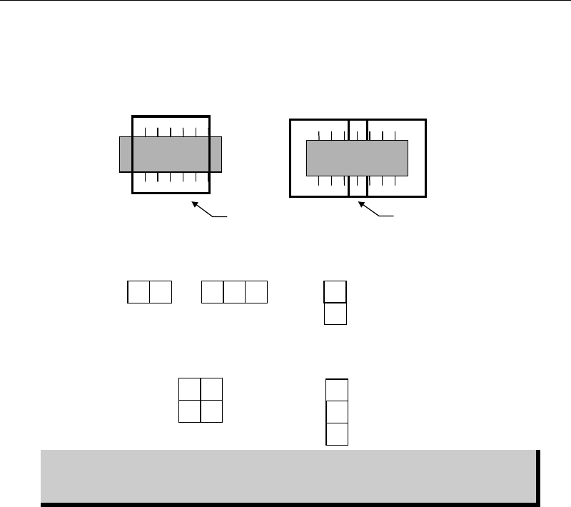
5-1-5-5 Multiple-view Process
Usually, the component image is captured as a whole picture. But when the component is too
large for the camera view, it can be captured separate pictures. In multiple-view process, the
head moves over the fixed camera for the number of views you have specified.
The figure below lists available view division patterns:
Component image data is created based on its packaging state. Therefore, view
division direction, horizontal or vertical, must be selected based on the
component packaging direction.
2
1
1
3
2
Three
vertical views
1
2
Two
vertical views
32
1
Three
horizontal views
Two
horizontal views
21
34
Four views
Multiple-view process allows for
covering the overall component.
Component is too large for
the camera view...
Camera view
overlapping
Chapter 5 Libraries
5-55
5-1-5-6 Dimensions Settings and Others
Common Settings
z Dimensions Settings
Enter dimensions-related data of the scan target. When placing a cursor at a setting field, an
explanatory graphic for the setting and its description are displayed in sub-windows.
Note: An item displayed in yellow suggests its setting is out of the valid range.
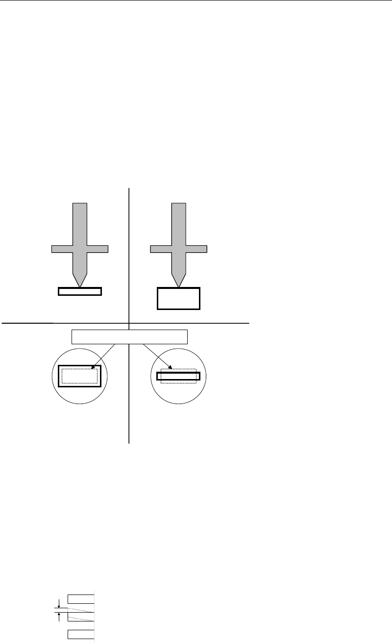
z Size Permission (1-100%)
The permission applied to the body size. Smaller the setting is, more severe the requirement
will be. Normally, specify 20% at "Size Perm." Set 30% at "Size Perm." for chip components with
the shorter side of less than 2.0mm, such as 1005 chip and 1608 chip. If the size of a component
is considerably irregular, use 40%.
Tilt placement: Permission
limit is exceeded.
Î
Retry
Normal placement
Bottom view
Side view
Nozzle
Minimum permission limit (dotted line)
z Offset Permission (1-100%)
The permission applied to the pickup position relative to the nozzle center. The default value
of 10% is set at "Offset Perm." for SOP, SOJ, PLCC, LCC, and QFP. If the offset is large, increase
this value.
z Lead Bend Permission
The permission applied to the horizontal lead bending.
Note: Default values are entered at Offset Permission and Lead Bend Permission in advance.