M20_Ope_E.pdf - 第180页
Chapter 5 Libraries 5-30 How To Perform ADA Action: ADA is performed via the Image Library edit wind ow. ① In the Image Library edit window, type the im age code and comment, and select the camera. ② Type the component…
Chapter 5 Libraries
5-29
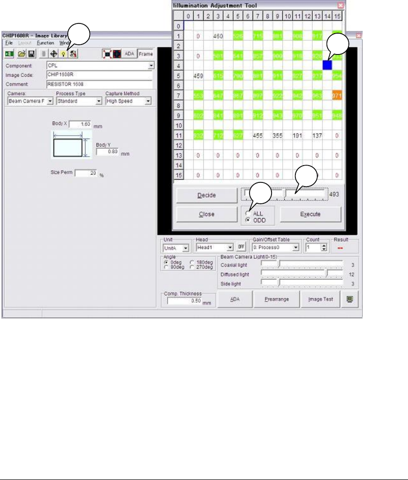
⑦ The score’s threshold value is entered automatically based on the measurement results.
(Indicated by “D”) This can be changed freely. For instance, if you want to narrow down
the measurement results, drag the threshold slide bar to the right (to higher score). Only
the higher score combinations will be displayed in color (in this example, combinations of
score 493 or higher will be displayed in color, since the threshold value is 493).
⑧ Click an appropriate illumination setting and then click <Decide>. The “main and sub” or
“Coaxial and Diffused” illumination will be set automatically.
⑨ Execute the image test, and check that the Vision window does not show any reflection of
the nozzles and a clear image of the component is displayed.
⑩ If you want to change the illumination settings, repeat steps ⑧ and ⑨.
Note: For the gain and offset, the initial values of the image data will be used. (“0” for chip
components, and “10” for leaded components such as ICs)
To change the gain/offset values, change them manually and then re-execute measurement.
5-1-2-6 ADA
ADA acquires various data required for image processing by measuring the component
automatically, and creates image data. Conventionally, component dimensions have to be
measured using calipers to enter image data. This is an inefficient method since it consumes a
lot of labor and time. Use of ADA reduces both labor and time, enabling efficient data creation.
■ Target Component Codes
Image codes for Chip, Transistor, Power transistor, SOP, SOJ, PLCC, LCC, QFP and BGA/CSP
(except white substrate BGA/CSP) components are supported. Four Terminal Search, Blob
process, CPL process and BGA and Connector are not supported.
A
B
C
D
Chapter 5 Libraries
5-30
How To Perform ADA
Action: ADA is performed via the Image Library edit window.
① In the Image Library edit window, type the image code and comment, and select the
camera.
② Type the component thickness in [Comp. Thickness] and select the head in [Head].
Note: On the M7, select a unit to use in [Unit].
③ Click <Prearrange> button to open the Prearrange. Through Prearrange, let the machine
head pick up a component
1
from the ST-F
2
or tray feeder. (You can manually attach the
component to the head as well.)
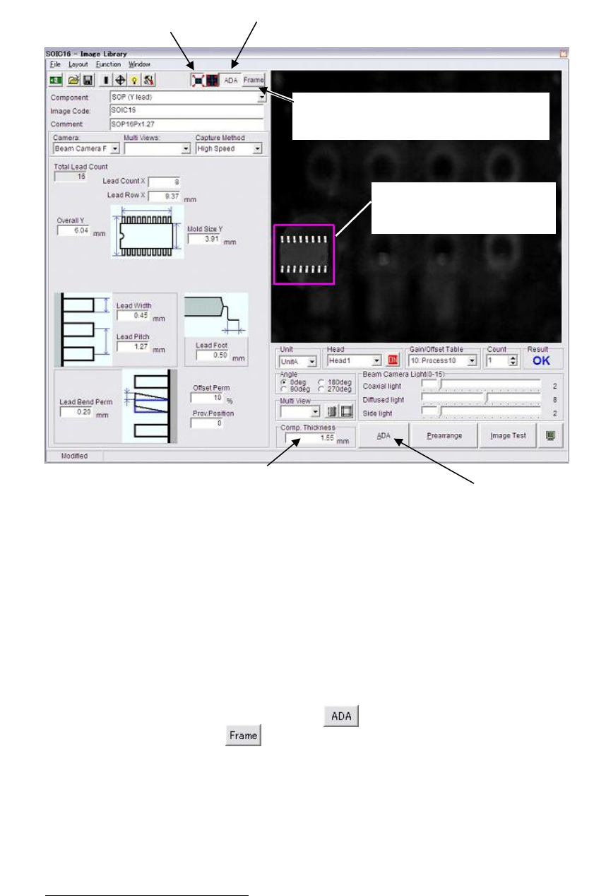
④ Click the <Full Screen Mode> button at the upper part of the window.
⑤ Click the <Area Select ADA Mode> button .
⑥ Click the <Frame> button . The component frame performed by the ADA is able to
appear in this VCS monitor.
⑦ Click and drag the ADA range. ADA is performed only within the specified range.
Note: On the M7, be sure to specify ADA range. It can prevent undesired images being included in
ADA range. No need to specify ADA range for the M6/M6ex/M6ez.
⑧ Click <ADA> button.
3
When you select the Fixed camera or Scan camera, the message
“Move the head to camera's scan position?” appears. Click <Yes> button.
1
Use a component free from deformities such as bent leads. Also it is recommended the pickup angle conforms
to the package angle.
2
Pickup direction of the component must conform to the packaged direction when set to the ST-F.
3
The camera illuminates only when capturing a component. The captured image is stored and displayed on the
VCS monitor.
Component thickness settin
g
is critical for ADA and ima
g
e test. When the
Thickness setting is entered to the component library, the setting is
displayed in this field. When not entered, the default “15.00” is displa
y
ed.
In this case, be sure to re-enter the correct value
.
⑤
On the M7, click the <Area Select ADA Mode> button.
Onl
y
when the <Full Screen Mode> is selected, the ADA
range specification is available.
④ Click the
<Full Screen Mode>.
⑥Click the <Frame> button. T
h
e component
frame performed b
y
the ADA is able to
appear in this VCS monitor.
⑦On the M7, click and dra
g
the
ADA ran
g
e. ADA is performed
only within the specified range.
⑧ Execute ADA.
Chapter 5 Libraries
5-31
⑨ When the process is successfully completed, [OK] is displayed in the Result box. Then the
message “Are you sure to overwrite?” appears. Press <Yes> button. When the process fails,
[NG] is displayed. In this case, follow the given message. See Chapter 15 MMI Messages.
⑩ Lastly, click <Image Test> button to execute image test. When the process is normally
completed, it proves the data is available for operation.
⑪ Click File>Save to register the data.
Note: On the M6/M6ex/M6ez, multiple-view process cannot be performed via the scan camera.
Note: When ADA is performed in multiple-view process, after the first sub-view is captured, select
[Multi View], “Subview2”, <Next> button to move on to the next sub-view. Repeat it for the
rest of sub-views. In ADA using multiple-view process, after executing ADA, the guide
window won’t be displayed. To display the guide window, click <Guide> button. While the
guide window is displayed, you cannot switch to other sub-view.