M20_Ope_E.pdf - 第177页
Chapter 5 Libraries 5-27 ④ Additionally, if it is failed to pick up the component from the tray, the following window will appear. Change the pickup point of the matrix, and then click <OK>. The pickup point is the…

Chapter 5 Libraries
5-26
5-1-2-4 Quick Prearrange
Use of this quick prearrange function makes it possible to automatically perform a series of
operations from the component pickup to the image test without use of the prearrange function
described previously.
Operations, such as attaching the nozzle to the head, pallet take-out from the tray feeder, and
component pickup are performed continuously.
Note: This function cannot be used unless data necessary for the image test is finished (arranged).
If the error message, “ ** data is not registered.”, appears, create necessary data.
Action:
① In the [Program], [Pickup data], or [Component data] window, click [Data Edit Utilities]
-> [Quick Prearrange] or the [Quick Prearrange] icon.
② The following window will appear.
To perform the feeder feed of the station, check on [Feed a component].
After that, click <Execute>.
③ Operations, such as attaching the nozzle to the head, pallet take-out from the tray feeder,
and component pickup are automatically performed continuously. After that, the image
test is then performed.
Note: If any nozzle, feeder, or pallet necessary for the image test is not prepared, relevant error
appears. If this occurs, prepare necessary items and perform [Quick Prearrange] again.
[Quick Prearrange]
icon
Chapter 5 Libraries
5-27
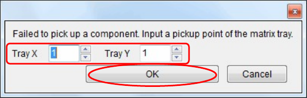
④ Additionally, if it is failed to pick up the component from the tray, the following window
will appear.
Change the pickup point of the matrix, and then click <OK>.
The pickup point is then changed to pick up the component again.
⑤ The image data window corresponding to the component will appear.
⑥ When the image test is completed and the image data window is closed, the component is
rejected or reused according to the [Reject/ Reuse] setting of the pickup data.
Additionally, the pallet is returned to the tray feeder.

Chapter 5 Libraries
5-28
5-1-2-5 Illumination Adjustment
The illumination adjustment tool supports the creation of illumination settings to be used for
image processing. It measures combinations of “main and sub” or “Coaxial and Diffused”
illuminations automatically and then allows the operator to select the most suitable setting.
This tool supports the processing of all the components and fiducial marks. This section
explains how to create component image data.
■ Illumination Adjustment Procedure
① Open the image data edit window for the target component. (Correct component
thickness must be entered.) Select Prearrange > [Set Default] / [Pick& Reject] and enter
the pickup-point (ST No.) to pickup the component with an appropriate nozzle.
② When creating new image data, first execute ADA to create temporary image data.
(Correct component thickness must be entered.)
Note: In the case of components not supported by ADA, necessary information must be entered
manually to create temporary image data.
Note: The illumination adjustment tool measures illumination settings in such a way that the size of
the target component can be recognized accurately. So accurate component size and lead width
must be entered in the image data.
③ Click [Illumination adjustment tool] button (indicated by “A”) in the image data edit
window.
④ The [Illumination adjustment tool] window appears, so select “ALL” to measure all the
combinations (256 combinations) or “ODD” to omit some measurements (64
combinations). (Indicated by “B”)
Note: Numbers “0” to “15” given on the vertical and horizontal lines indicate “main and sub” or
“Coaxial and Diffused” illumination settings (in 16 steps), respectively.
⑤ Click [Execute] button. A message “Execute searching for the proper Illumination?”
appears, so click <OK> to start measurement.
⑥ When measurement is complete, results will be displayed. (The results shown below are
when ODD is selected.)
Green cells indicate the illumination settings that are judged to be appropriate, and
orange cells indicate the setting with the maximum sore.
Note: If measurement is performed with “ODD” selected, some cells will be empty since some
combinations are omitted.
However, if the results in empty cells are within the appropriate illumination setting range,
they can also be used. (Example: blue cell indicated by “C”)