M20_Ope_E.pdf - 第238页
Chapter 5 Libraries 5-88 5-1-6 Nozzle Library (Nozzle D ata) Menu: Program>NozzleData Progarm>ComponentData>NozzleData Register nozzle-related data. Window: File>Save: Saves the edited data. Tool>AirPressu…
Chapter 5 Libraries
5-87
Comment: Any appropriate comment.
* Up to 40 characters can be entered.
Brightness: Threshold value to see white or black of the inspection point;
Higher score than this represents white, lower black. (standard :
127)
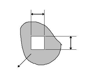
Search Area X: Length of the inspection area in the X (horizontal) direction.
Usually enter 1 to 2mm.
* Increment : 0.01mm
Search Area Y: Length of the inspection area in the Y (vertical) direction.
Usually enter 1 to 2mm.
* Increment : 0.01mm
S
earch area X
Search area Y
Bad mark
Note: Define smaller search area than the bad mark size; The mark location may vary from board to
board.
Action:
① In the Bad Mark Data dialog box, select the bad mark color (white/black) for [Image
Type] by clicking <Mode> button.
② Enter all the required data.
③ Click Prearrange>Teach&Move Pallet to teach the coordinates of the bad mark center.
④ Adjust the Gain, Offset, and Inside/Outside Light setting so the bad mark image is shot
clearly.
⑤ Click <Image Test> button to execute image test. Confirm the test ends in success.
⑥ The bad mark should ideally score Measure=255 for white color, and Measure=0 for black
color in the image test. Re-adjust the illuminator setting and redo the image test until the
score approaches 255/0 as possible.
⑦ Move the main teach camera to capture the resist part around the bad mark. Adjust the
Inside/Outside Light setting and execute image test until Measure=0(for white color)/
Measure=255(for black color) can be obtained.
Note: If Measure=255 and 0 cannot be obtained even the illuminator setting is properly adjusted, add
the Measure value for the bad mark and the resist part, divide the value by 2, and enter the
value to [Brightness] of the Bad Mark Data dialog box.
⑧ Save the data.
For white bad marks, when the brightness in the specified search area at "Search Area Y" and
"Search Area X" is more than "Brightness", OK is issued.
For black bad marks, when the brightness in the specified search area at "Search Area Y" and
"Search Area X" is less than "Brightness", OK is issued.

Chapter 5 Libraries
5-88
5-1-6 Nozzle Library (Nozzle Data)
Menu: Program>NozzleData
Progarm>ComponentData>NozzleData
Register nozzle-related data.
Window:
File>Save: Saves the edited data.
Tool>AirPressure: Measures the vacuum pressure of each nozzle. For information, see
Chapter 8.
Nozzle: Nozzle name.
Example: NOZZLE_P004, NOZZLE_P020
* Up to 14 characters can be entered.
Comment: Any annotation for the nozzle.
* Up to 20 characters can be entered.
Nozzle No.: Number used in a nozzle name. Serves to link the nozzle library and
the component library. 1 to 20 are used as standard nozzle numbers.
Example: NOZZLE_P004 -> 4, NOZZLE_P020 ->20
Choke Threshold: Threshold for detecting nozzle choking. Use the default setting
normally.
* Increment : mmHg
Pick Threshold: Threshold for detecting improper pickup. Use the default setting
normally.
* Increment : mmHg
Directionality: For a non-directional nozzle, enter “Free” (default). For a directional
nozzle, enter “Fixed” or “Fixed (reversible)”.
“Fixed”: Non-reversible type. Component pickup is possible only at a
pre-determined angle.
“Fixed (reversible)”: Reversible type. Component pickup is possible
when the nozzle is rotated 180 degrees from the pre-determined
pickup angle.
Inner Diameter: Nozzle inner diameter.
* Increment : 0.01mm
Vacuum Check: Specify whether to perform abnormal pressure detection
(Enabled(Pickup/Choke)/Disabled/Enabled(Choke Only)). When
“Enabled(Pickup/Choke)” is specified, the system checks for nozzle
choking or pickup error by inspecting the vacuum pressure when
exchanging nozzles or picking up/placing the component. When "
Enabled (Choke Only)" is specified, if the vision process has been
successfully done, placement will be performed regardless of the
pickup pressure. This function is useful when the pickup pressure is
not stable because the pickup surface is not flat.
Special Nozzle: Normal: normal nozzle
Side Y: side pickup nozzle, offset in Y direction
Side X: side pickup nozzle, offset in X direction
To use a side pickup nozzle, enter the offset value in the [Side Pickup
Offset] cell.
Delay for Vacuum ON: For pickup with a Side Pickup Nozzle, set the delay time after the
completion of the Side Pickup Offset to start suction.
Range: 50 to 100 ms
To enable this function, select “Side X” or “Side Y” in the [Special
Nozzle] cell.
Grip Length: Specify the length of the gripping part of a special nozzle
(Side pickup nozzle).
Side Pickup Nozzle: 3.0 to 5.5 mm
Chapter 5 Libraries
5-89
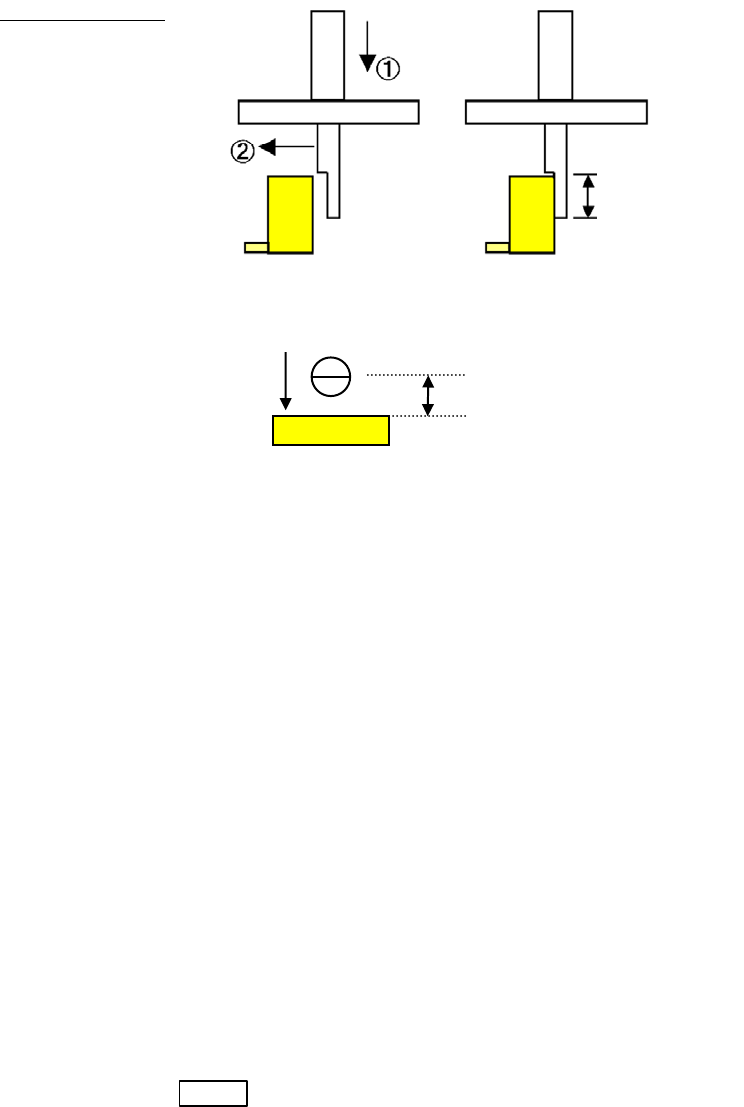
Side Pickup Offset: Specify the offset value for a side pickup nozzle to move after the head
has been lowered. When the head is to move in the negative direction
after it has been lowered, a negative (-) value shall be specified.
Example:
“Side Y” is specified in [Special Nozzle] (Side Pickup Nozzle, offset in
Y direction) and a negative value is entered in [Side Pickup Offset]
① The head moves down at the offset point in the Y direction from the
pickup point.
② The head moves in the negative Y direction.
Grip Length
(Side View)
(Top View)
Comp. Remain Check: This function checks if a component remains on the nozzle instead of
being placed on a board by vision process with the scan/beam camera
or by vacuum pressure.
Disabled
Vacuum pressure
Vision process
“Enable or Disable” is specified in Comp.Remain Check by Vission
Process or Comp.Remain Check by Vacuum Pressure in the User
Parameter>Functions(1).
ANC ID: Specify the ID number for an ANC hole for a specially designed
nozzle.
Remain Check Code: Specify the image code for comp. remain check.
Specifying the Pickup Angle for Directional Nozzles
To specify the pickup angle for the directional nozzle, enter the angle to [Package Angle] of the
tray library or the packaging library.
Note: In this case, create the component image data at the nozzle angle 0 degree (the angle the nozzle is
seated in ANC).
Timings When Automatic Nozzle ID Recognition is Performed
Automatic nozzle ID recognition is performed in the below three situations:
1. When you select Manual>Nozzle Info. and click <Scan Nozzles> button.
2. When you press START button. (only when the nozzle ID is not still acquired.)
3. When the job run is stopped (cycle stop) and re-started after the ANC channel is actuated
(open/close).
Grip Length
Side Pickup Offset
②
Side Pickup Nozzle