M20_Ope_E.pdf - 第285页
Chapter 9 Running a Job 9-13 z Component count setting of PS-MS3 The component count of PS-MS3 is managed st ick by stick. Since [Component Count] tab doesn’t provide feeder names by which we can id entify which stick of…

Chapter 9 Running a Job
9-12
[Count/Program]:
Component count used in the program.
[Producible PCB]:
Producible PCB count using the remaining components.
z [Details] tab
Shows the component linkage information and the component
counts (programmed, loaded, and remaining) for each component.
Components are classified according to their feed styles.
17. [Component Count] tab:
The [Component Count] tab page can display station information
for ST-F, ST-R, and CTF-X. For “Component Code”, “Pallet” and
“ST No.”, the data entered in the data edit window will be referred
to and displayed. For “Pallet”, [P1(P2,P3…)#] (pallet No.), “X1
Start” and “Y1 Start”, the pallet library will be referred to and the
corresponding data will be displayed.
Based on this setting, check the following points.[Feeder Skip]
“0” in the [Feeder Skip] in ST-F/ST-R means the feeder can be used, and “1” shows the feeder
cannot be used.
When pickup/vision-process error occurs at one feeder consecutively, the system sends the
head to another feeder having the same component. At this point, “1” is set to the [Feeder Skip].
This only happens when [Use other feeder when pickup/vision-process error occurs] in
UserParameter>Alternate is enabled.
[Feeder Skip] can also be set manually.
Note: For information on alternate function, see Chapter 9, User Parameter, Alternate.
[Priority]
Basically, if there are plural feeders that have the same component code, the use of feeders are
in ascending order of the pickup No. However, you can prioritize a certain feeder by setting
“1” to [Priority].
[Priority] : 0=Not Prioritize, 1=Prioritize
Note: To apply the setting to the job run. click the <Apply> button.
Component count setting is correct (ST-F, ST-R).
[Set Count] indicates the number of components set at the beginning. [Remain Count] serves as
the component reduction counter. At the component changeover, [Set Count] and [Remain
Count] are set to the same value. As the job run proceeds, [Remain Count] is reduced as the
components are used.
To copy all [Set Count] settings to each corresponding [Remain Count] setting, click <Reset
All> button. To copy only the selected [Set Count] setting to [Remain Count] setting, click
<Reset Line> button.
z When running a particular program for the first time
When you open the Run dialog box, you will see the defaults in [Set Count] and [Remain
Count] fields. When necessary, change [Set Count] settings by typing and click <Reset All>
button. All [Set Count] settings are copied to the corresponding [Remain Count] settings. To
copy only the selected [Set Count] setting to [Remain Count] setting, use <Reset Line> button.
z When running a particular program for the second or later time
Basically [Set Count] and [Remain Count] settings are preserved from the previous
production sessions. But there are some exceptions as described below.
Either before or during the production session, if you modify pickup data of either
[Component Code], [Feed Style], [ST No.], [Feeder/Pallet], order the pickup data is
entered, or the number of pickup data entries, [Set Count] and [Remain Count] settings
are reset to the defaults.
Chapter 9 Running a Job
9-13
z Component count setting of PS-MS3
The component count of PS-MS3 is managed stick by stick. Since [Component Count] tab
doesn’t provide feeder names by which we can identify which stick of PS-MS3 is referred to
(PS-MS3-A, PS-MS3-B, ...), [ST No.] setting herein is utilized. Based on [ST No.] setting of
PS-MS3-E (where PS-MS3-E is electrically connected), [ST No.] of the remaining sticks are
assigned as shown in the below table.
PS-MS3- A B C D
E F G H I
ST-F -2 -2 -1 -1
ST No. of PS-MS3 (
where PS-MS3-E is
electrically connected
)
+1 +1 +2 +2
ST-R +2 +2 +1 +1
ST No. of PS-MS3 (where PS-MS3-E is
electrically connected
)
-1 -1 -2 -2
Example: When PS-MS3 is electrically connected at ST No. 20 of ST-R, [ST No.] setting for each stick is
assigned as follows.
PS-MS3- A B C D
E F G H I
ST No. 22 22 21 21
20 19 19 18 18
Note: When a stick is emptied and you replace it with a new stick, press the PS-MS3’s FEED switch
to index a component.
To enable the system to give an alarm in component shortage (residual sensing), enter the
correct component count to [Set Count] and [Remain Count] before running a program.
The Shortage Alarm setting in Program>PickupData takes effect only when
[Set Count] and [Remain Count] settings in the Run dialog box are entered
correctly.
When you enter [Set Count] and [Remain Count] settings correctly, you can utilize the
inventory information. See the following section for information.
The initial pickup point for each tray matches Run>ComponentCount setting.
The default of both [X Start] and [Y Start] is “1”. You can modify this default if necessary. See
Editing Default Values for the Job Run later in this chapter.
z When running a particular program for the first time
When you open the Run dialog box, you will see the default “1” entered in [X Start] and [Y
Start] fields.
z When running a particular program for the second or later time
Basically [X Start] and [Y Start] settings are preserved from the previous production
sessions. But there are some exceptions as described below.
Either before or during the production session, if you modify pickup data of either
[Component Code], [Feed Style], [ST No.], [Feeder/Pallet], order the pickup data is
entered, or the number of pickup data entries, [X Start] and [Y Start] settings are
defaulted to “1”.
Note: Even when you modified only the pickup data of tape feeders, [X Start] and [Y Start] settings
will be defaulted.
Chapter 9 Running a Job
9-14
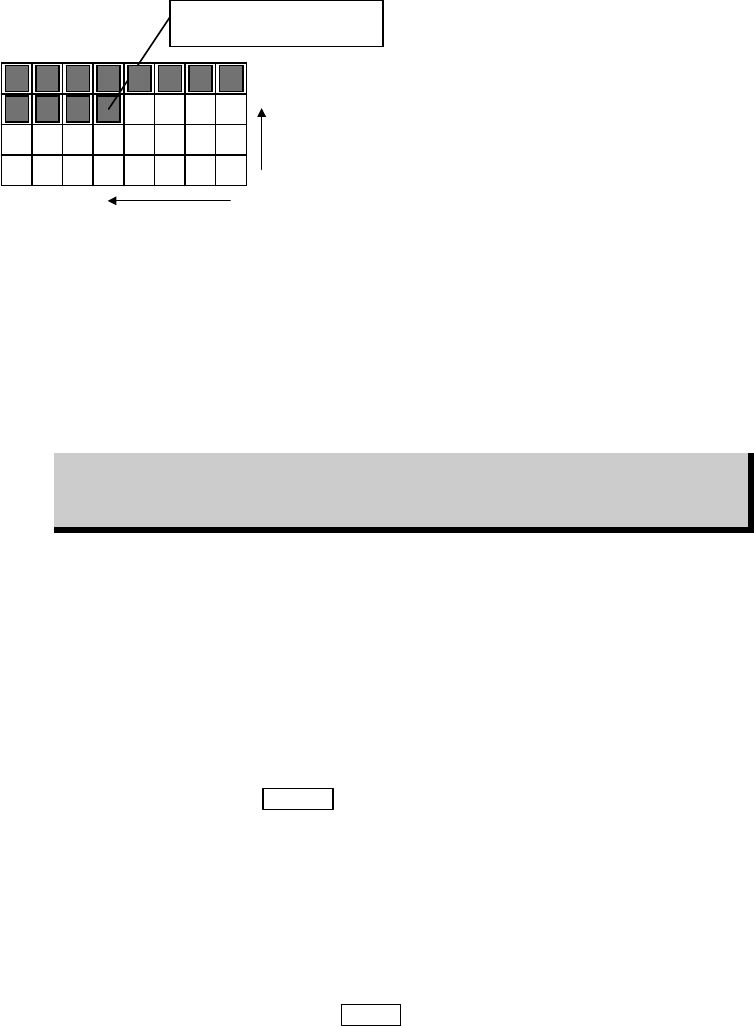
You can specify [X Start] and [Y Start] by typing. The below example shows a half-used tray in
use of the pickup pattern of "X One-way". (PalletLibrary>Pattern)
To start from this component, enter
X Start = 5, Y Start = 3.
Y Start = 3
X Start = 5
You can also specify the initial pickup position for each pallet. When there is a pallet link
assignment, the order [X Start]/[Y Start] setting is entered conforms to the order of the link
assignment in the pallet library. For information about link, see Chapter 5, Pallet Library.
By default, a job starts from the first pallet of a link assignment. But you can also specify where
to start. For example, to start from the pallet of [P3#], enter "3" to [Start Position] field.
To enable the system to give an alarm in component shortage (residual sensing), enter [Start
Position], [X Start], and [Y Start] settings correctly.
The Shortage Alarm setting in Program>PickupData takes effect only when
[Start Position], [X Start], and [Y Start] settings in the Run dialog box are
entered correctly.
When you enter [Start Position], [X Start], and [Y Start] settings correctly, you can utilize the
inventory information. Information on the inventory information is described earlier in this
chapter.
Component Shortage and Feeder Changeover
In [Component Count] tab, [Remain Count] field of the emptied pickup point turns red.
When replenishing components to the emptied feeder, the component count setting should be
updated. When setting a new tray to a pallet, its initial pickup point setting is defaulted (X
Start=1, Y Start=1) by pressing
SETUP switch.
z Component Count Setting
When replenishing components to an emptied feeder, type in the component count in
[ST-F/R]>[Set Count] and click <Reset Line> button. Then click <Apply Count> button to
determine.
When setting a new tray to a pallet, type in the initial pickup point to [X Start], [Y Start] of the
pallet. Then click <Apply Count> button to determine.
Note: To reset the component count, press the
STOP switch.
Note: It is not necessary to click <Apply Count> button for each setting you have changed. When all
the settings have been changed, click <Apply Count> button only once.
Note: For more information of component changeover paused by an alarm, see Chapter 10.