M20_Ope_E.pdf - 第427页
Chapter 14 Intelligent Feeder 14-27 14-4-2 Auxiliary Explanation for Relocatable Function ■ Displaying the Remaining Count in the Production Window When the relocatable function is used, the pickup points vary with the f…
Chapter 14 Intelligent Feeder
14-26
14-4 Data
14-4-1 Feeder LED Display Contents
The LED on feeders indicates the feeder status and meaning of errors.
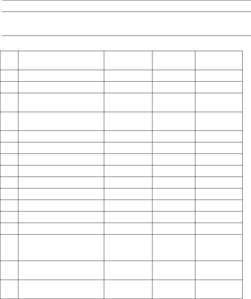
No. Status Color LED
Blinking
frequency (ms)
1 Wire-breakage None --- ---
2 Energized (Note) Yellowish green
Lit ---
3
Intelligent feeder recognized
(Note)
Green Lit ---
4
Component identification NG
(Mis-location)
Pink Flash 100
5 Component confirmation OK
Green Blink 500
6 Not used for production Blue Blink 500
7 Not registered to database Blue Flash 100
8 Component Exhaustion Orange Lit ---
9 Shortage alarm Orange/green
Lit alternately 500
10 Pickup NG skip Orange Flash 100
11 Feeder trouble Pink Lit ---
12 Removal lock Orange Blink 500
13 Simplified check Light blue Flash 100
14
Alternative position
Pickup-undefined lane
(Relocate)
Green/blue Lit alternately 500
15
Alternative position
Pickup-defined lane (Relocate)
Green/pink Lit alternately 500
16
Not used for production
Pickup-defined lane (Relocate)
Blue/pink Lit alternately 500
Note: These feeders are recognized as intelligent feeders when "START" button in the production
window is clicked. If a feeder is not recognized as the intelligent feeder, its feeder LED will be
lit continuously in yellowish green.
Chapter 14 Intelligent Feeder
14-27
14-4-2 Auxiliary Explanation for Relocatable Function
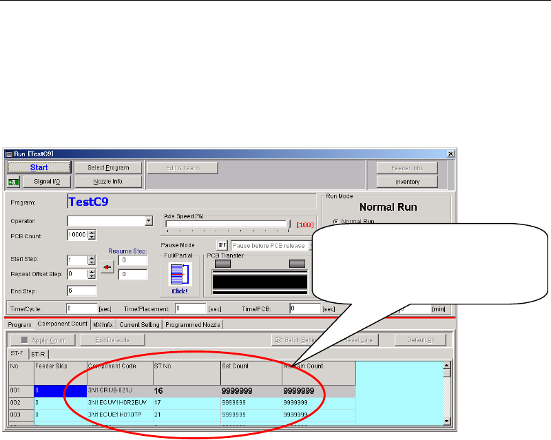
■Displaying the Remaining Count in the Production Window
When the relocatable function is used, the pickup points vary with the feeder arrangement. So,
if the actual feeder (component) arrangement differs from the program data, the remaining
count and some other parameters given in the production window are not interlocked with the
actual feeder arrangement. The remaining count is controlled by the ID database.
Management data cannot follow feede
r
location changes arranged by the
feeder arrangement of Relocatabilit
y
function.
■Performance record
Although the pickup points vary with the feeder arrangement if the relocatable function is
used, the Performance record is accumulated without change to components (feeder
arrangement) taken into account. So, if the actual feeder (component) arrangement differs from
the program data, the Performance record will also differ from the actual data.
■Prior-check
A prior-check to see whether or not components set in a feeder can be picked up will not be
performed at the start of production. For instance, if components are located outside the head’s
movable range, a “feeder NG: retry limit arrival” error will occur since the head cannot pick up
the components. (However, this error does not apply to the database, therefore, the head will
restart to pick up components if the components are relocated in an area where they can be
picked up.)
■Skip Setting Method
It is not possible to make skip setting for pickup points individually. To skip certain
components, make skip setting per line in the mount data.
Chapter 14 Intelligent Feeder
14-28
■Setting the Pickup Offset
Even if a pickup coordinate offset is set for the pickup data of a component, it will be cleared if
that component (feeder) is relocated to another position by the relocatable function. (The offset
will remain effective if the component is relocated in the same position as that in the pickup
data.) So when setting components (feeder) in a position that differs from the pickup data,
attention must be paid to the pickup coordinate misalignment.
→To set a pickup coordinate offset for the components (feeder) that are set in a position that
differs from the pickup data, execute the following steps.
①Halt production and activate the "Edit & Teach" mode.
②Select Program > Pickup Data window.
③Since components set in a position that differs from the pickup data have been
added to the pickup data (one line is added), check the pickup point No. and set the
pickup coordinate offset.
④Select Save > Apply > START. This will perform pickup operation with the offset
reflected.
Note: If the relocatable function is used, only the data of the currently executed program can be
edited in halt edit mode during production. The changes (updates) to the program data are
reflected continuously during production. However, they will not be reflected if production is
canceled, since they are also canceled at that time.
■Restrictions on Use of Side Pickup Function and Angle Settable Nozzle
Components for which the side pickup function has been set should not be set in any positions
other than those set in the program data (pickup data). This also applies to the components that
are to be picked up by an angle settable nozzle (i.e. Nozzle Library > "Directionality" setting is
other than “Free” is set).