M20_Ope_E.pdf - 第176页
Chapter 5 Libraries 5-26 5-1-2-4 Quick Prearrange Use of this quick prearrange function makes it possible to automatically perform a series of operations from the component pickup to the image test without use of the pre…
Chapter 5 Libraries
5-25
ANC tab
Refer to 9. Running a Job>ANC Initial Setting.
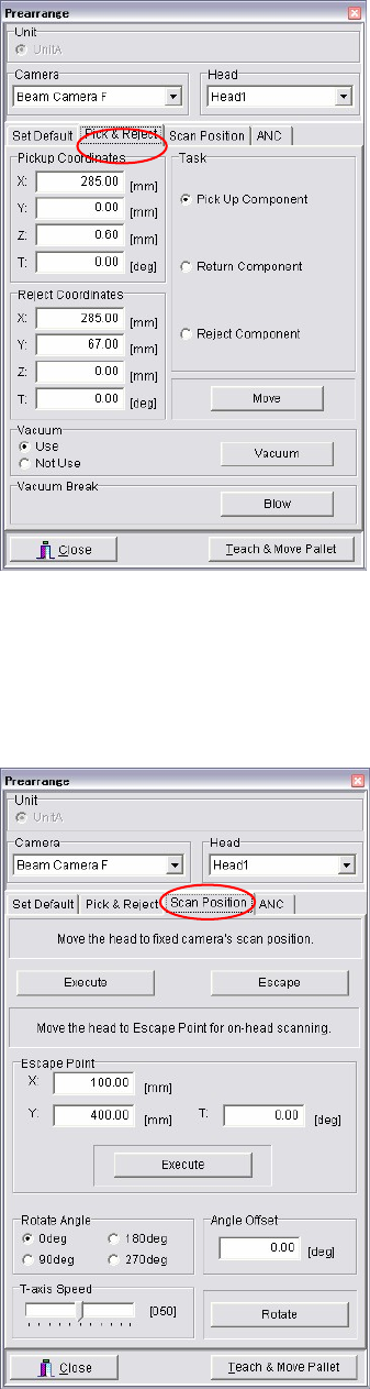
■ Pick & Reject tab
When the cursor is at a setting field of [Pickup
Coordinates] or [Reject Coordinates], the Teach
dialog box can be opened by right-clicking the
mouse. By using the Teach dialog box, you can
adjust the coordinates or move the tray pallet.
To pick up a component, select [Task], <Pick Up
Component>, <Execute>. After the pickup, the head
moves to the Head Escape coordinates.
After performing ADA or image test, a tray
component can be returned to the tray by selecting
<Return Component>. Also, a component can be
re
j
ected to the re
j
ect coordinates b
y
selectin
g
<Re
j
ect
Component>.
You can also manually attach the component to the
nozzle. The specified head starts vacuuming by
selecting [Vacuum], <Use>, <Execute>. Attach the
component in the direction of the package state.
To remove the component manuall
y
, move the head
to the machine front and place your hand below the
head. Then select [Vacuum], <Not Use>, <Execute>
to stop the vacuum and receive the component. If
the component keeps stuck to the nozzle, select
[Vacuum Break], <Use>, <Execute>.
■ Scan Position tab
[Move the head to fixed camera’s scan position.] is
available only when a fixed camera is specified.
Click <Execute> button and the component-loaded
head moves down for 5mm. Then the head assembl
y
travels to the scan position over the fixed camera. In
this state, select the VCS Control dialog box and
click <ADA> or <Image Test> button. Clicking
<Escape> button enables the head to move up to its
XY movement height.
When the scan camera is specified, you can specify
the head position where ADA or image test is
performed on-head. Enter coordinates of the head
position to [Escape Point] with teach entry
(right-click the mouse). Manual entry from the
keyboard is also available.
To rotate the component, select a rotation angle
under [Rotate Angle] and choose <Rotate> button.
To rotate by different angle from the suggested
options, enter offset angle to [Degree Offset], which
is added to the specified an
g
le for obtainin
g
desired
angle.
To adjust the T-axis speed, before executin
g
rotation,
specify per cent of the maximum speed (=100%) by
dragging the slider of [T-axis Speed].
* The function [Move the head to Escape Point for
on-head scanning.]does not work for now.

Chapter 5 Libraries
5-26
5-1-2-4 Quick Prearrange
Use of this quick prearrange function makes it possible to automatically perform a series of
operations from the component pickup to the image test without use of the prearrange function
described previously.
Operations, such as attaching the nozzle to the head, pallet take-out from the tray feeder, and
component pickup are performed continuously.
Note: This function cannot be used unless data necessary for the image test is finished (arranged).
If the error message, “ ** data is not registered.”, appears, create necessary data.
Action:
① In the [Program], [Pickup data], or [Component data] window, click [Data Edit Utilities]
-> [Quick Prearrange] or the [Quick Prearrange] icon.
② The following window will appear.
To perform the feeder feed of the station, check on [Feed a component].
After that, click <Execute>.
③ Operations, such as attaching the nozzle to the head, pallet take-out from the tray feeder,
and component pickup are automatically performed continuously. After that, the image
test is then performed.
Note: If any nozzle, feeder, or pallet necessary for the image test is not prepared, relevant error
appears. If this occurs, prepare necessary items and perform [Quick Prearrange] again.
[Quick Prearrange]
icon
Chapter 5 Libraries
5-27
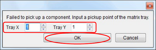
④ Additionally, if it is failed to pick up the component from the tray, the following window
will appear.
Change the pickup point of the matrix, and then click <OK>.
The pickup point is then changed to pick up the component again.
⑤ The image data window corresponding to the component will appear.
⑥ When the image test is completed and the image data window is closed, the component is
rejected or reused according to the [Reject/ Reuse] setting of the pickup data.
Additionally, the pallet is returned to the tray feeder.