M20_Ope_E.pdf - 第248页
Chapter 5 Libraries 5-98 z Automatic-component-height teaching by vacuum pressure Here explains the automatic teaching method in addition to the manual teaching to determine the component height as mentioned steps ⑧ thro…
Chapter 5 Libraries
5-97
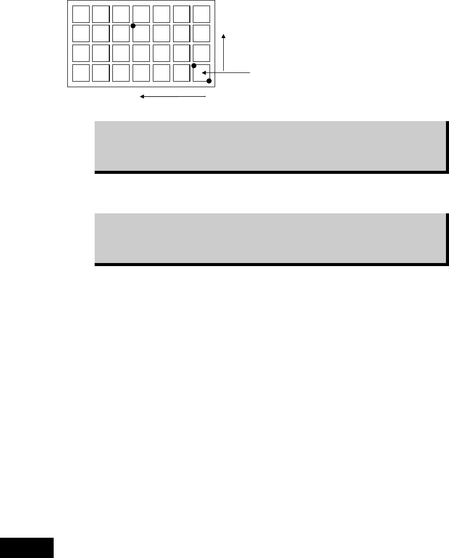
⑥ Perform three-point teach for the points illustrated below:
Y=3
X=4
Ori
g
inal
p
icku
p
p
oint
Three teach points are graphically
suggested on the Teach dialog
box.
While the main teach camera cannot cover the entire tray, it can handle
three-point teach. Within the camera work range, teach the farthest point from
the original pickup point as the third teach point. The third teach point must
correspond to the Count X/Y settings you have entered.
Then the system calculates the original pickup coordinates (Original X/Y) and the component
pitch (Pitch X/Y). The result is displayed in the corresponding fields.
After performing the three-point teach, correct the Count X/Y settings to the
original settings. Otherwise, the system calculates the component count
according to the Count X/Y settings used for the three-point teach, resulting in
component mis-counting.
See the following Caution 1 before operating step
⑧
to
⑬.
⑦ Teach the component height. This teaching is for Z height of the component, therefore the
nozzle needs to be set on a head at first.(recommended nozzle type : No.05 or No.06;
without a rubber.)
⑧ Select “XY axes” in [Axis], and select the head referred to in the previous step in [Head].
Select “1” for both [X Pos.] and [Y Pos.], then click <Trace> to move the head to the
original pickup point.
⑨ Place a sheet of paper with thickness of ordinary photo-copy paper over the component.
Under [Axis], enter “Z axis”. Lower the nozzle slowly toward the component. If necessary,
slow down the axis speed using [Axis Speed] setting. When the nozzle reached the paper,
try to pull the paper to see the nozzle height is proper. When the paper is lightly caught
between the nozzle and component, the nozzle height is best adjusted.
⑩ Subtract 0.1mm from the Z height obtained in the previous step. This means the nozzle
pushes down the component for 0.1mm.Type in the value to TrayLibrary > [Component
Height] field.
⑪ Close the Teach dialog box by clicking <X> button.
⑫ Click File>Save to save the data. Close the tray library editor by clicking <X> button.
The procedures of manual teaching mentioned in steps ⑧ through ⑬ have the risk of collision
of the nozzle against the component. Therefore it is recommended to measure the component
thickness with a caliper and enter the thickness in the Component Height manually.
Caution 1
Chapter 5 Libraries
5-98
z Automatic-component-height teaching by vacuum pressure
Here explains the automatic teaching method in addition to the manual teaching to determine
the component height as mentioned steps ⑧ through ⑬ above. By the automatic teaching, the
mounter checks the vacuum and determines the component height where the vacuum
increases.
Action:
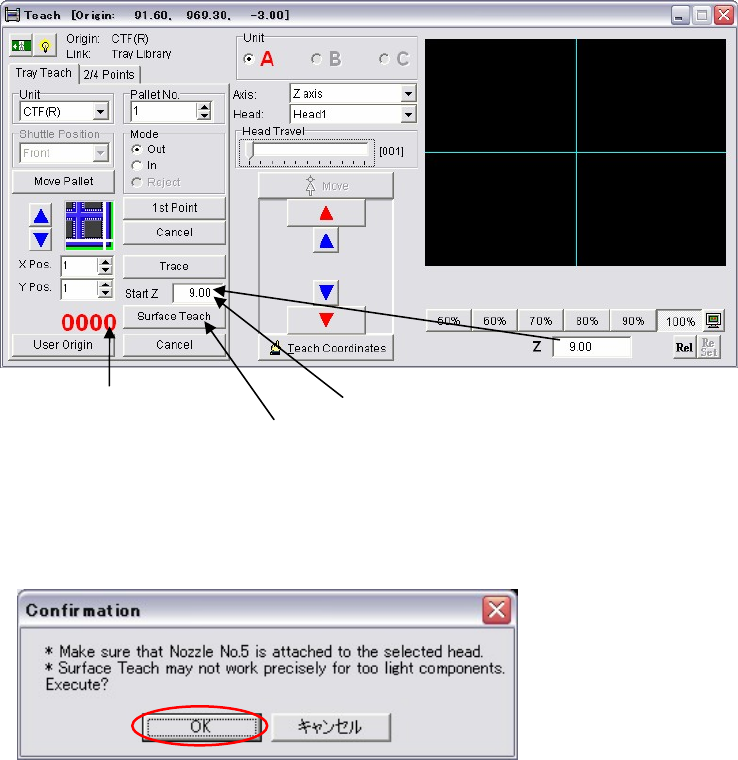
① Attach a nozzle type 05 to the head No. specified in [Head].
Note: Be sure to use a nozzle type 05 which does not have a rubber ring.
② Select “XY axes” in [Axis], and select the head No. which the nozzle type 05 is attached in
[Head]. Select “1” for both [X Pos.] and [Y Pos.], then click the <Trace> to move the head
to the original pickup point.
③ Select “Z-axis” in [Axis], and select the head No. which the nozzle type 05 is attached in
[Head].
Move down the nozzle slowly toward the component surface by confirming visually.
Stop the nozzle when it gets closer to a few millimeters to the component surface.
Note: At this time just close the nozzle to the component surface. Do not let the nozzle touch or hit
the component.
④ Enter this height of step ③ in [Start Z].
⑤ Click the <Surface Teach> button.
The following dialog box appears. Press the <OK> button.
Then the nozzle automatically starts moving down slowly from the height of the [Start Z]
with vacuum is on.
It shows the head [Vacuum].
Click the <Surface Teach> button.
Enter the height in [Start Z].
Chapter 5 Libraries
5-99
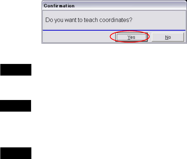
⑥ When the nozzle touches the component, the vacuum pressure rises. At the same time, the
motion of the nozzle stops and the following dialog box appears.
When you click the <Yes> button, the Z coordinate is determined as the component height
and registered in the tray data. After this process, the nozzle moves up automatically.
Teaching the component height has the risk of collision of the nozzle against the component.
Therefore it is recommended to measure the component thickness with a caliper and enter the
thickness in the Component Height manually.
When you start the surface teach, first, the nozzle travels to the coordinates of the [X Pos.] and
the [Y Pos.]. Then the nozzle moves down to the height of the [Start Z] and starts the
automatic-component-height teaching.
Before performing the surface teach, be sure that a component exists in the tray pocket where
the component height is measured. Otherwise the bottom of the empty tray would be
determined as the component height. It may result in nozzle and head damage.
Do not make the [Start Z] value too low. Otherwise the nozzle may hit the component surface
and may result in nozzle and head damage.
Note: Initial value of the [Start Z] is 20mm.
If you start the surface teach at this height, the process takes more than 10 minutes. Start
moving from the height close to the component surface. (See step ③.)
Note: Lighter components are not appropriate for this automatic-component-height teaching because
they may be sucked up before the nozzle reaches to the component surface. It may result in
determining higher component height than the actual height. For such lighter components,
manually measure the thickness with a caliper and enter it in the Component Height.
Caution 3
Caution 1
Caution 2