M20_Ope_E.pdf - 第226页
Chapter 5 Libraries 5-76 ② T he c om ponent i s displaye d grap hi c all y ( whi t e i ndi cat es ex i st in g ba l l s , black in di cat e s n on-exi s ting ball s). Ball s s wi t ch f rom white t o bl ack and vic e ver…
Chapter 5 Libraries
5-75
Note: When
Measured ball size < Theoretical ball size x (100 - Ball size permission) ÷ 100
or
Measured ball size > Theoretical ball size x (100 + Ball size permission) ÷ 100,
an error occurs.
Theoretical ball size = Ball size x Ball reduction ratio ÷ 10
z Ball Reduction
Standard: 100
Unit: %
Note: Used for compensating the measured ball size when the imaged ball is reduced in size due to
lighting conditions.
z Process Type
0: Use this process type for BGA/CSP components with regular aligned balls. Enter an acurate
pitch in [Ball Pitch]. Much faster than the process 1.
1: Use this process type for components with somewhat irregular ball aligned balls such as flip
chips, etc. It is also possible to use for BGA/CSP components. Slower than the process 0.
z Ball Check
9: Presence (outmost)
Vision-align the component based on its outermost ball square. Check for ball presence only
for the outermost ball square.
10: Presence&Damage(all)
Vision-align the component based on its outermost ball square. Check for ball presence, ball
size, and ball diameter for all the balls.
11: Presence(all)
Vision-align the component based on its outermost ball square. Check for all the ball
presence for all the balls. Faster than the process 9.
12: No Checks
Ball checks are not performed.
z Starting Side
0: Auto
The side with the largest number of balls and lesser missing balls is selected for the first side
for ball check.
1: Upper Side
2: Right Side
3: Lower Side
4. Left Side
Select the first side for ball check when the side with the largest number of balls is not
reliable due to misalignment, etc.
Chapter 5 Libraries
5-76
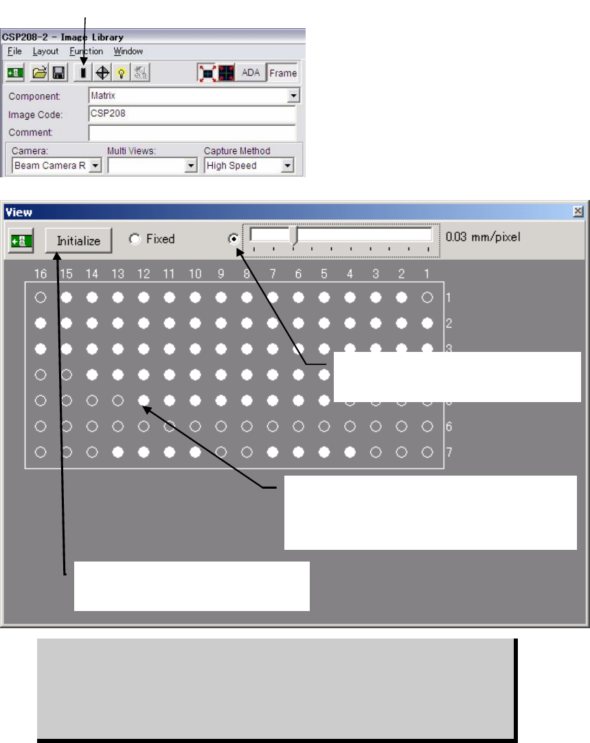
② The component is displayed graphically (white
indicates existing balls, black indicates non-existing
balls). Balls switch from white to black and vice versa
alternately each time they are clicked.
④Selecting here enables you to change the
graphic size using the scroll bar.
⑤Clicking <Initialise> button restores the
original ball arrangement (i.e. all the balls
including unnecessary ones are present).
z Random Ball Arrangement
Menu: ImageLibrary>View
Action: To specify the random ball arrangement for BGA/CSP components, execute the following
steps.
① Click <View> button in the image data edit window to open the View window.
② The component is displayed graphically with all balls present, according to the X/Y ball
count, ball size, ball pitch specified in the image data edit window.
③ Click unnecessary balls (i.e. balls that do not exist on the actual component) with the
mouse. They will turn from white to black. Black balls will be ignored during image
processing, so make sure that unnecessary balls are clicked to provide the actual ball
arrangement.
④ If the graphic display size is too large or too small, slide the scroll bar to reduce or enlarge
the size.
⑤ To restore the original ball arrangement (i.e. all the balls including unnecessary ones are
present), click <View> button.
BGAs can be handled either via the BGA mode or the BGA/CSP mode. But we
recommend you to use the BGA/CSP mode for the following reasons. When
using the BGA/CSP mode, missing balls assignment can be easily performed
by using the ball numbering system used in the component catalog. Also the
limitations stated on page 5-72, Note, won’t occur when the BGA/CSP mode is
used.
① Click the <View> button.
Chapter 5 Libraries
5-77
Comparison between BGA mode and BGA/CSP mode
BGA mode
Upper-right Ball
Coordinate
Lower-left Ball
Coordinate
Ball-less Square
(Missing Data)
Full grid -- -- Not required
Perimeter grid Required Required Not required
Partial grid -- -- Required
BGA / CSP mode
Perimeter grid Partial grid Random ball
Full grid Not required Not required Not required
Perimeter grid Required Not required Not required
Partial grid Required Required Not required
Random ball Not required Not required Required
Illuminator Settings
Increased quantity of the side light results in brighter side portion and then center portion.
Adjust the quantity so that the center of a ball is slightly dark.
Note: Do not use the outside light.
Note: The best way: Prepare a ball-missing BGA component. Adjust illuminator settings so that the
image of normal balls can be clearly captured, while ball-missing portion is unseen.
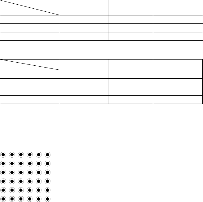
Ball Pattern
Setting
Ball Pattern
Setting