SME_Jig_User_Guide(Eng_Ver1).pdf - 第29页
2-3 Prepare 2.1.2. Power Supply and Lighting Power and lighting sections have a connector for the power supply , a dial adjusting t he brightness of the lightin g, and a USB port for communication between the calibrat io…
2-2
User's Guide For Tape Feeder Calibration Jig
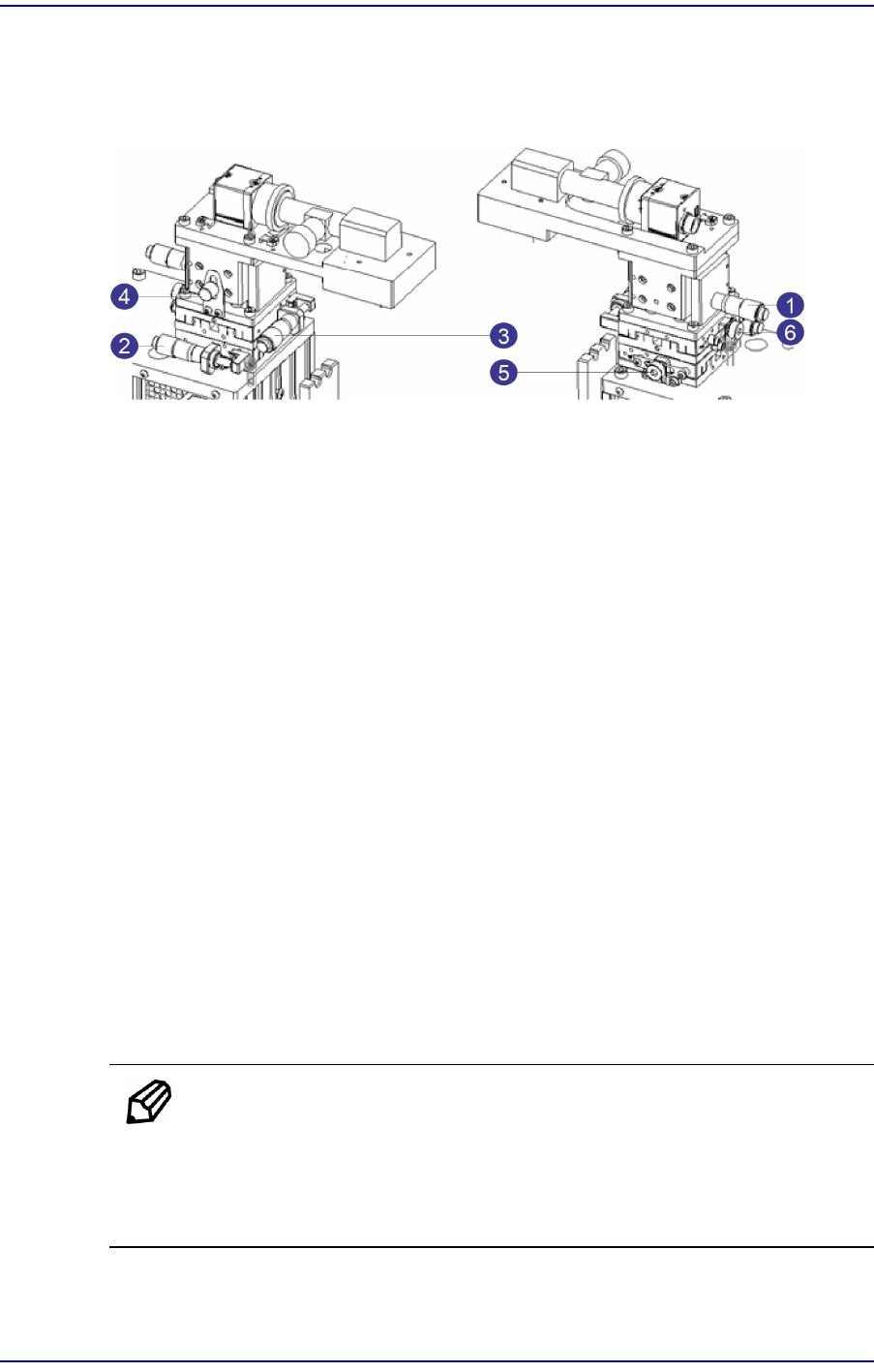
2.1.1. X, Y and Z Stages
A camera is assembled to the X, Y and Z stages. They can be moved to the X, Y and Z
axes using a adjustment pin.
1: Z-axis Adjustment Pin
2: Y-axis Adjustment Pin
3: X-axis Adjustment Pin
4: Z-axis Fixing Pin
5: Y-axis Fixing Pin
6: X-axis Fixing Pin
w Z-axis Adjustment Pin
Moves the stage to the Z-axis.
w Y-axis Adjustment Pin
Moves the stage to the Y-axis.
w X-axis Adjustment Pin
Moves the stage to the X-axis.
w Z-axis Fixing Pin
Fixes the stage Z-axis
w Y-axis Fixing Pin
Fixes the stage Y-axis
w X-axis Fixing Pin
Fixes the stage X-axis
Memo
It is possible to adjust the stage X, Y and Z axes with the upper base
cover protecting the camera and stage being assembled.
Use a flat head screwdriver when fastening a fixing pin for the X, Y
and Z axes.
2-3
Prepare
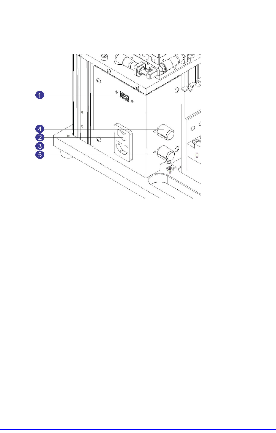
2.1.2. Power Supply and Lighting
Power and lighting sections have a connector for the power supply, a dial adjusting the
brightness of the lighting, and a USB port for communication between the calibration jig
and computer.
1: USB Port for CAN Communication
2: Main Power Supply Switch
3: Main Power Supply Connector
4: Coaxial Lighting Adjustment Dial
5: Fiducial Lighting Adjustment Dial
w USB Port for CAN Communication
Communication port for the USB cable connecting the computer and calibration jig
w Main Power Supply Switch
Switch that turns on/off the power supply to the calibration jig
w Main Power Supply Connector
Power supply connector connecting the power cable
w Coaxial Lighting Adjustment Section
Dial adjusting the brightness of the coaxial lighting
w Fiducial Lighting Adjustment Section
Dial adjusting the brightness of the fiducial lighting
2-4
User's Guide For Tape Feeder Calibration Jig
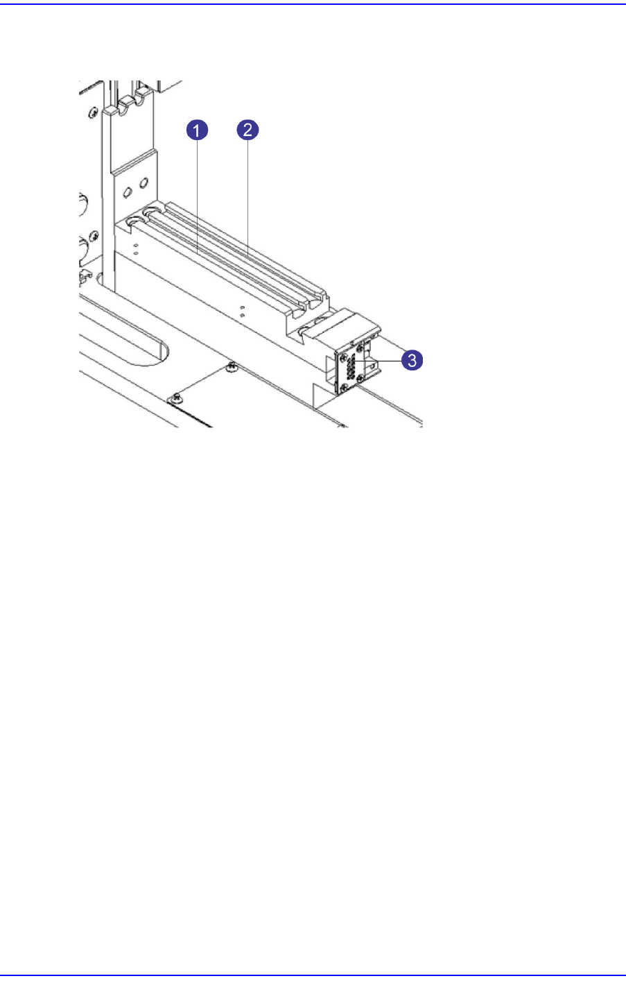
2.1.3. Feeder Base
The feeder base is where tape feeders are installed and has slots and connectors.
1: No. 1 Slot
2: No. 2 Slot
3: Feeder Base Board
w No. 1 Slot
Slot where the master feeder and the feeder to be calibrated are installed
w No. 2 Slot
Guide slot used to install a large feeder
w Feeder Base Board
Provides power supply and communication to the feeder installed in the No. 1 slot.