SME_Jig_User_Guide(Eng_Ver1).pdf - 第36页
3-4 User's Guide For Tape Fe eder Calibration Jig 4. Double cli ck the icon to run the cali bration jig program. 5. Run the cal ibration jig program a nd manipulate the program in the following o rder: 1) Click the …
3-3
Tape Feeder Calibration
w When calibrating W4P1, 0402 and 8mm feeders
w When calibrating 12mm/16mm feeders
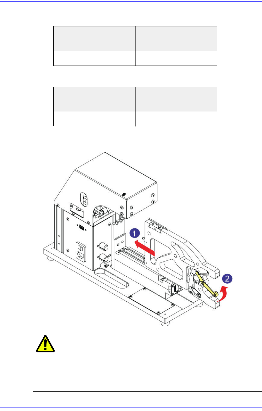
3. After ensuring the master feeder has come into close contact with the front plate of the
calibration jig, push the clamp lever up to fix the master feeder at the feeder base.
Caution
When inserting the master feeder into the feeder slot of the
calibration jig, moving the clamp lever up with a chip or
foreign material being jammed may cause the clamp lever
or link to bend. If the clamp lever or link is bent, replace it
without fail before using the master feeder.
Placement position of the
master feeder
Placement position of the
feeder to be calibrated
Left (#1) Slot Left (#1) Slot
Placement position of the
master feeder
Placement position of the
feeder to be calibrated
Right (#2) Slot Left (#1) Slot
3-4
User's Guide For Tape Feeder Calibration Jig
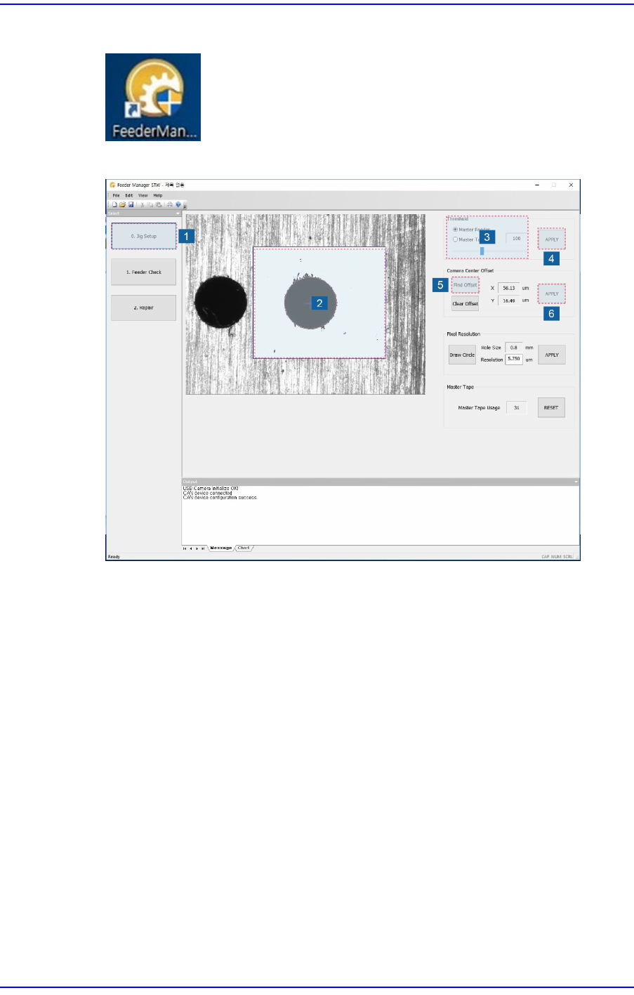
4. Double click the icon to run the calibration jig program.
5. Run the calibration jig program and manipulate the program in the following order:
1) Click the <Jig Setup> button.
2) Set the inspection area in the vision window. Dragging the mouse while clicking
the left button of the mouse will display the area.
3) Set the coaxial and fiducial lighting of the calibration jig. Then select the <Master
Feeder> option button in the <Threshold> area of the program and manipulate the
slider bar to perform setup so that the origin mark of the master feeder can be seen
clearly in the vision window.
If the origin mark of the master feeder is out of focus, ensure the image viewed in
the vision window is in focus by manipulating the Z stage of the calibration jig.
4) Click the <Apply> button to save the set value.
5) Perform adjustment so that the origin mark of the master feeder corresponding to
the tape feeder to be calibrated comes to the center of the vision window by
moving the XY stage of the calibration jig.
Adjust the XY stage by clicking the <Find Offset> button in the <Camera Center
Offset> area so that the distance between the center of the vision window (gray
crosshair) and the center of the origin mark of the master feeder (green crosshair)
will be less than 50μm.
3-5
Tape Feeder Calibration
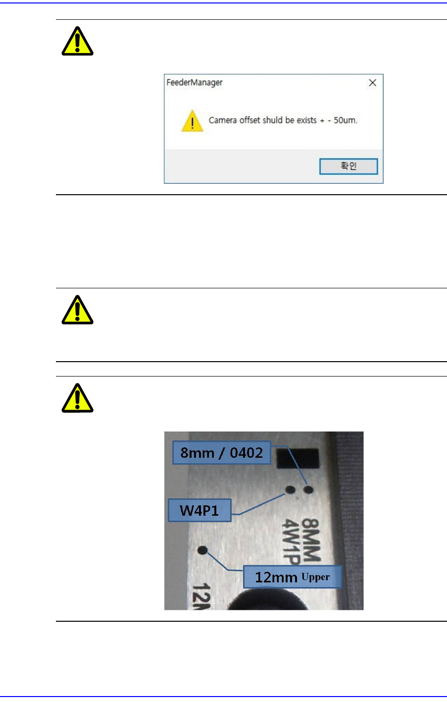
Caution
An alarm message is displayed when the vision recognition
criterion (± 50μm) is exceeded.
6) Click the <Apply> button to save the offset value. If the size of the origin mark to
be taught is different from the size of the origin mark displayed in the vision
window, click the <DrawCircle> button and input a value in the <Resolution> edit
box to adjust the circle size so that the origin mark to be taught will be the same as
the origin mark displayed in the vision window.
Caution
When delivering the calibration jig, the size of the origin
mark displayed in the vision window is set by default, so do
not adjust the origin mark size if possible.
Caution
The origin mark position of the master feeder differs
depending on the types of tape feeders.