SME_Jig_User_Guide(Eng_Ver1).pdf - 第49页
3-17 Tape Feeder Calibration Figure3.1 When Inspection R esult is Good Figure3.2 When Inspection R esult is No t Good w When the inspection result is ’X NG’ Set the eccentric pin of the feed er again referring to the &qu…
3-16
User's Guide For Tape Feeder Calibration Jig
1) Check whether the hole position is correctly recognized repeatedly by clicking the
<Grab> button 3~5 times. When the origin of the master feeder hole changes in
the vision window, adjust the threshold of the master tape again.
2) Click the <Homing> button to perform homing of the feeder.
3) Click the <Start Inspection> button to inspect the part supply accuracy of the
feeder. Starting the inspection will display the <Start Inspection> button as the
<Stop Inspection> button, and the vision system recognizes the master hole
position after the feeder has performed feeding 80 times.
Memo
In order to stop the inspection of the part supply accuracy of the
feeder, click the <Stop Inspection> button. However, stopping the
inspection will reset the feeding count and inspection results entirely.
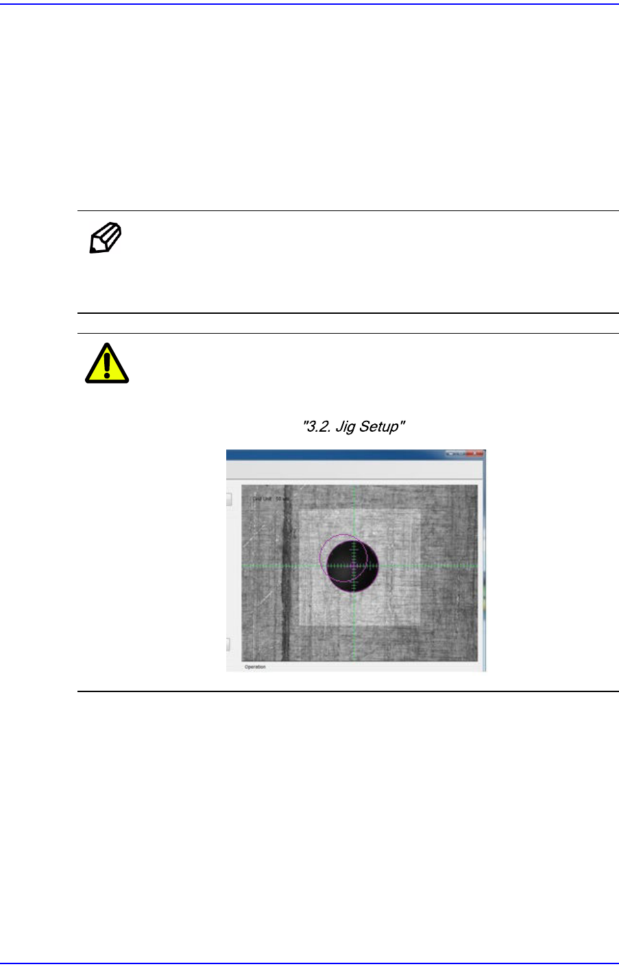
Caution
If the feeder hole position recognized by the vision system
is found to be incorrect by clicking the <Grab> button, a
serious problem may occur. Set the origin of the tape feeder
referring to .
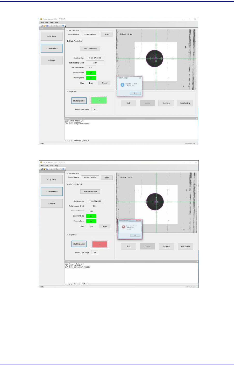
7. Completing the inspection will display the inspection result in the screen as shown in
the following screen.
3-17
Tape Feeder Calibration
Figure3.1 When Inspection Result is Good
Figure3.2 When Inspection Result is Not Good
w When the inspection result is ’X NG’
Set the eccentric pin of the feeder again referring to the "5.3.3. Adjustment of X
Eccentric Pin of Tape Feeder".
w When the inspection result is ’Y NG’
Initialize the sensor referring to "3.4.3. Mapping Inspection" and perform
mapping inspection. If the inspection results are found to be NG more than 2
times, solve the problem referring to "6.1. Problems and Measures".
3-18
User's Guide For Tape Feeder Calibration Jig
3.4. Tape Feeder Calibration (Repair)
When the main board of the feeder is replaced due to defective supply accuracy, or the
index motor, index gear or sprocket components were reassembled or replaced, calibrate
the tape feeder without fail by initializing the feeder sensor and performing mapping
inspection.
The tools necessary for tape feeder calibration are as follows:
w Calibration jig
w Calibration software
w Feeder to be calibrated
w Master tape
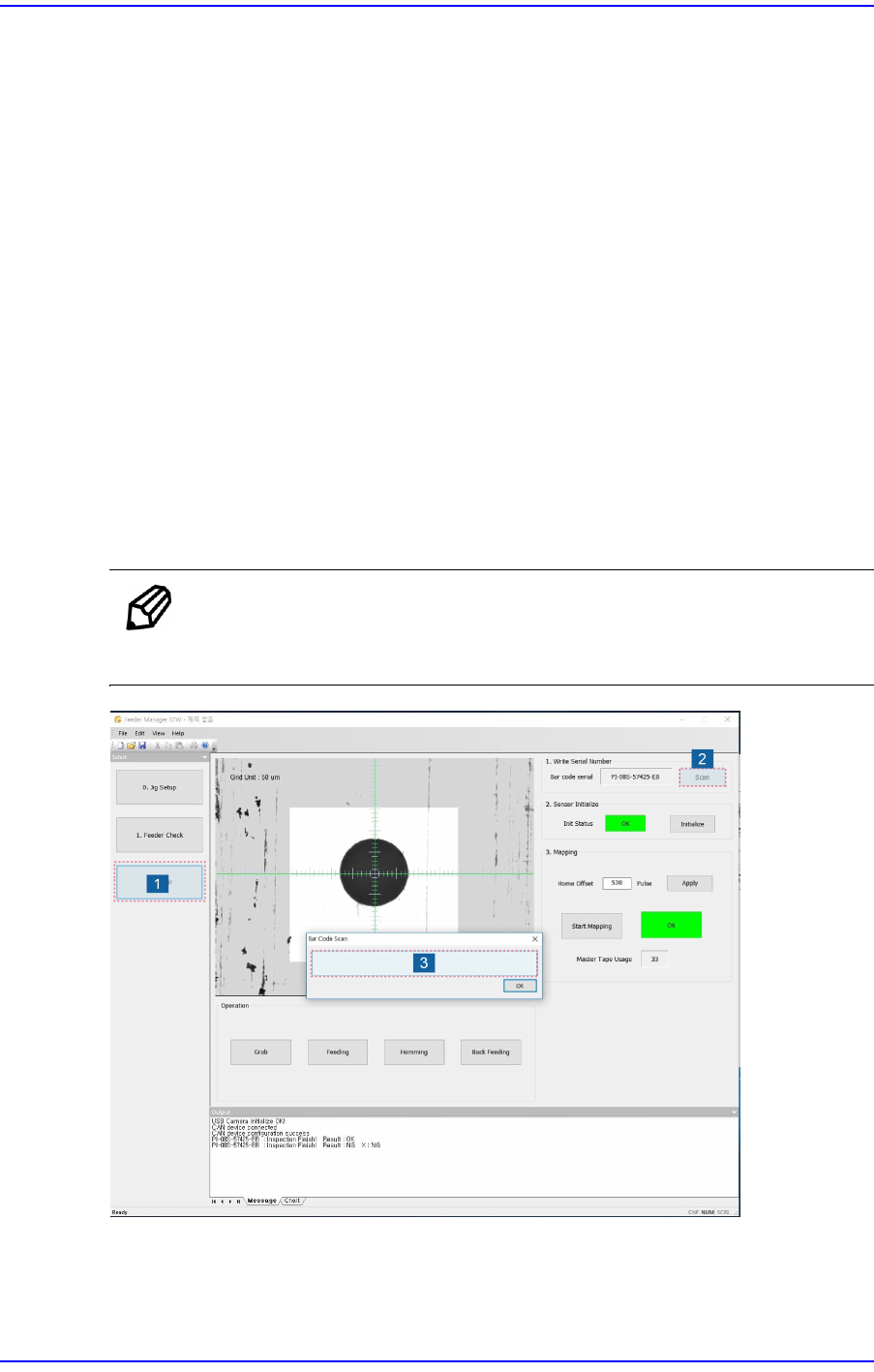
3.4.1. Change Serial Number (Write Serial Number)
When the serial number was lost due to main board replacement and data loss, the serial
number saved in the tape feeder main board can be changed by performing the following
procedure:
Memo
Changing the serial number will delete the existing serial number
saved in the tape feeder main board.
1. Click the <Repair> button.
2. Click the <Scan> button to enable the barcode scan window in which the serial
number is to be inputted.