SME_Jig_User_Guide(Eng_Ver1).pdf - 第82页
5-6 User's Guide For Tape Fe eder Calibration Jig Cauti on When adjusting the X eccentric pin, i nsert the shortest part of the 2.5 mm hex wrench into the hexagonal hole. Incorrect insertion of the 2.5 mm hex wrench…
5-5
Maintenance
5.3.3. Adjustment of X Eccentric Pin of Tape Feeder
When performing part supply accuracy of a feeder or mapping inspection, if the inspection
result is ’X NG’, adjust the X eccentric pin of the tape feeder in the following order:
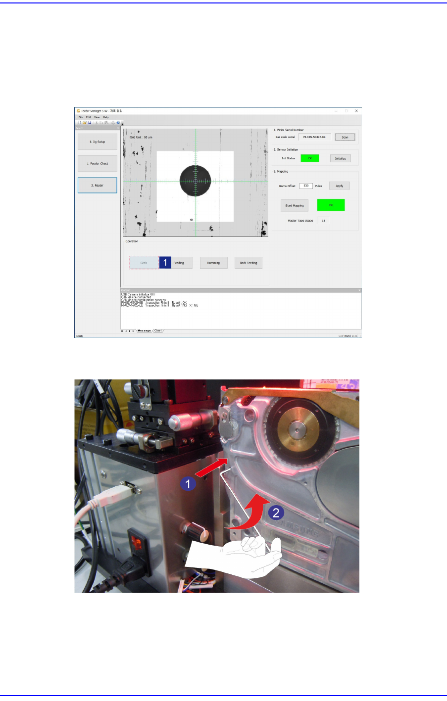
1. After inserting the master tape into the tape feeder, run the calibration jig program and
click the <Grab> button to check the center position of the master tape hole.
2. Insert a 1.5 mm hex wrench into the set screw fixing the X eccentric pin and turn it
counterclockwise to unscrew the set screw.
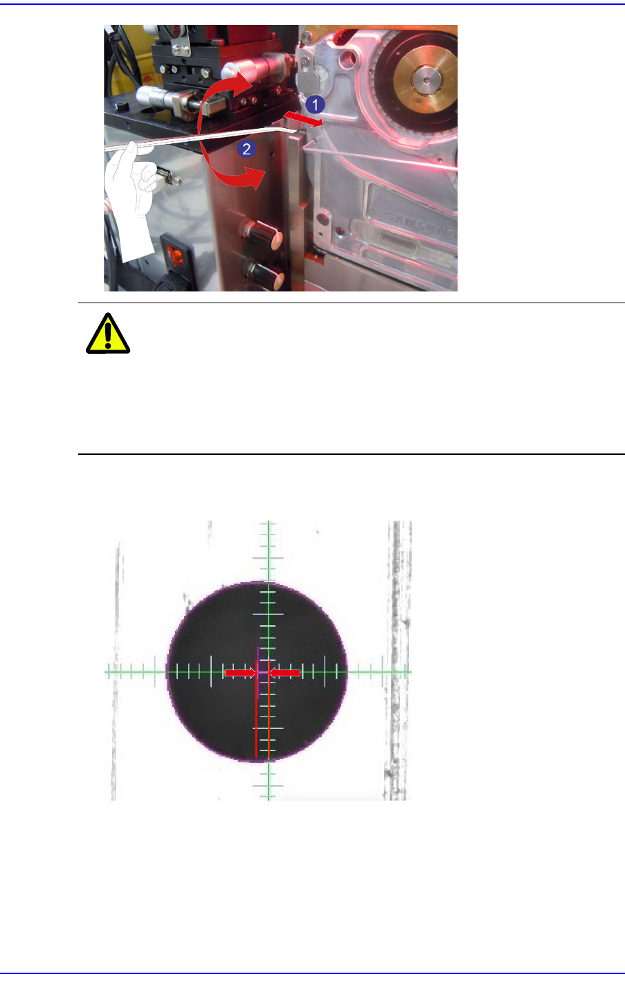
3. There is a hexagonal hole at the front of the X eccentric pin. Insert a 2.5 mm hex
wrench and turn it clockwise or counterclockwise to adjust the X eccentricity.
5-6
User's Guide For Tape Feeder Calibration Jig
Caution
When adjusting the X eccentric pin, insert the shortest part
of the 2.5 mm hex wrench into the hexagonal hole.
Incorrect insertion of the 2.5 mm hex wrench into the hex
hole of the X eccentric pin may damage the hex hole of the
X eccentric pin.
4. In the vision window, adjust the X eccentric pin so that the spacing between the master
tape hole center and the green crosshair center will be less than ±1 cell.
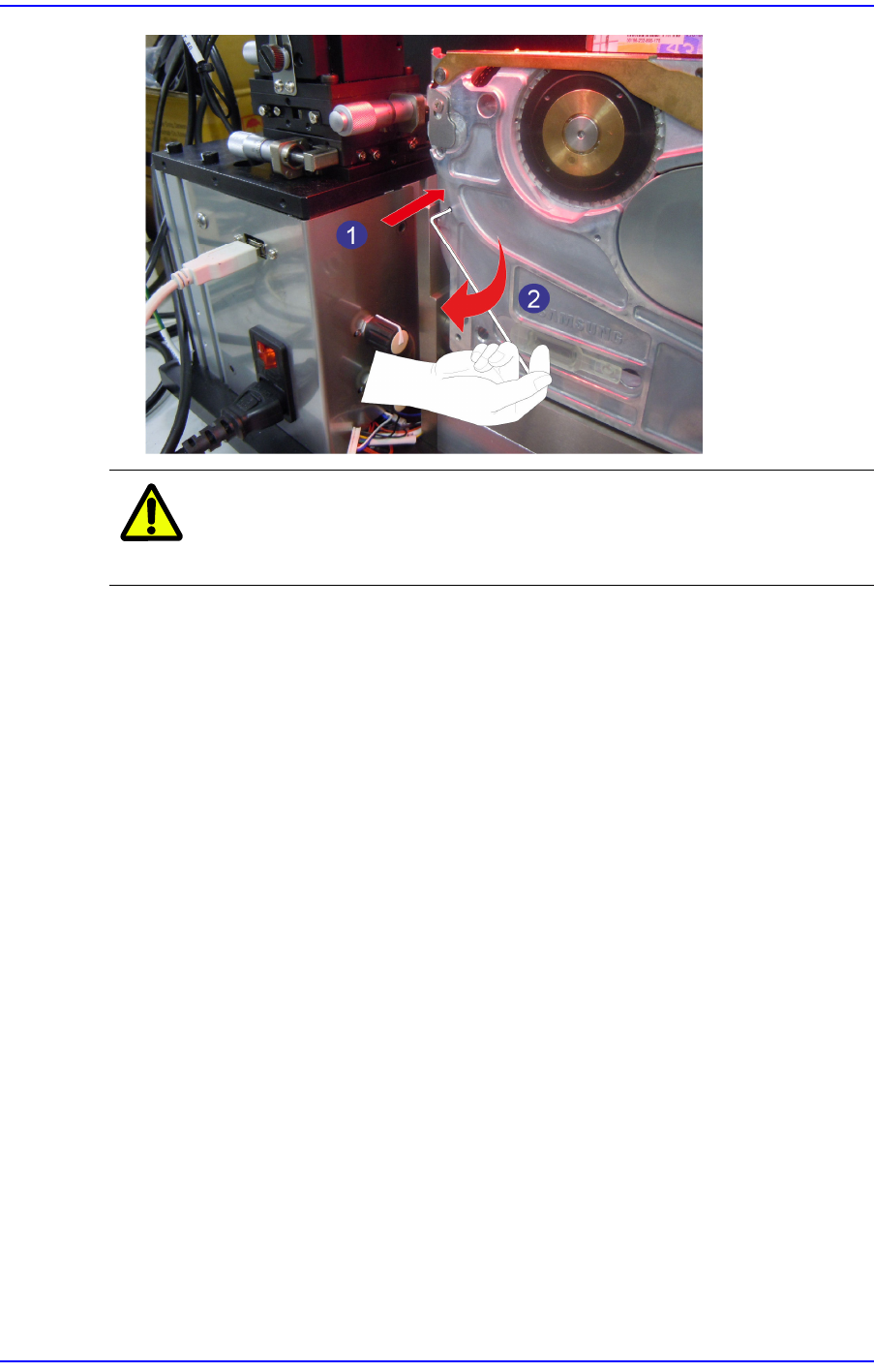
5. After removing the 2.5 mm hex wrench used for the adjustment of the X eccentric pin,
insert a 1.5 mm hex wrench into the set screw and turn it clockwise to fix the set screw.
5-7
Maintenance
Caution
Fixing the set screw by applying excessive force may
damage the screw.