SME_Jig_User_Guide(Eng_Ver1).pdf - 第34页
3-2 User's Guide For Tape Fe eder Calibration Jig 3.2. Jig Setup (Jig Setup) Perform setup so that the calibration jig camera teaches the or igi n mark of the master feeder . T he tools required to t each the origin…
3-1
Tape Feeder Calibration
Chapter3. Tape Feeder Calibration
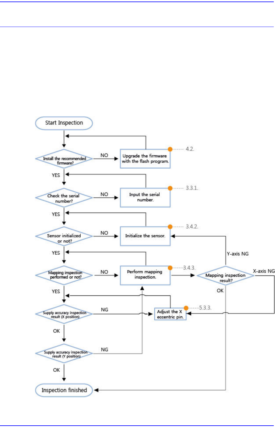
3.1. Flow Chart for Tape Feeder Calibration (Flow Chart)
It is possible to check the part supply accuracy of a feeder by calibrating feeders
periodically and maintaining the feeder in an optimum state.
In particular, when the main board of the tape feeder was replaced, or the index motor,
index gear and sprocket parts were reassembled or replaced, the corresponding feeder
must be calibrated.
The feeder calibration procedure is as follows:
3-2
User's Guide For Tape Feeder Calibration Jig
3.2. Jig Setup (Jig Setup)
Perform setup so that the calibration jig camera teaches the origin mark of the master
feeder. The tools required to teach the origin mark of the master feeder are as follows:
w Calibration Jig
w Calibration Software
w Master Feeder
Caution
w If a microchip is on the upper surface of the feeder base when
teaching the origin mark of the master feeder, a calibration error
of +50 ~ +80μm may occur.
w Placing the master feeder with a microchip jammed between the
master feeder and feeder base will make it difficult to check
visually whether a microchip is jammed or not. Therefore, clean
the feeder base before inserting feeders.
w For more details about calibration jig cleaning, refer to ”5.2.2.1.
Removal of Foreign Materials on Feeder Base / Vertical Plate”.
Remove any foreign materials on the master feeder and feeder
base using a brush or air gun.
The method to teach the origin mark of the master feeder is as follows:
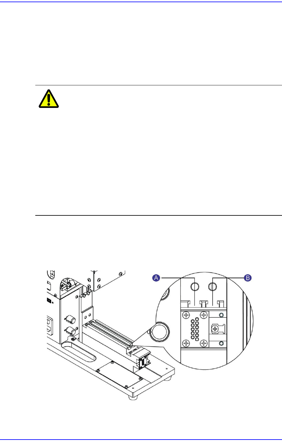
1. Turn on the power supply to the calibration jig.
2. Insert the master feeder into the feeder base slot according to the type of feeders whose
origin is to be set.
1: Left (#1) Slot
2: Right (#2) Slot
3-3
Tape Feeder Calibration
w When calibrating W4P1, 0402 and 8mm feeders
w When calibrating 12mm/16mm feeders
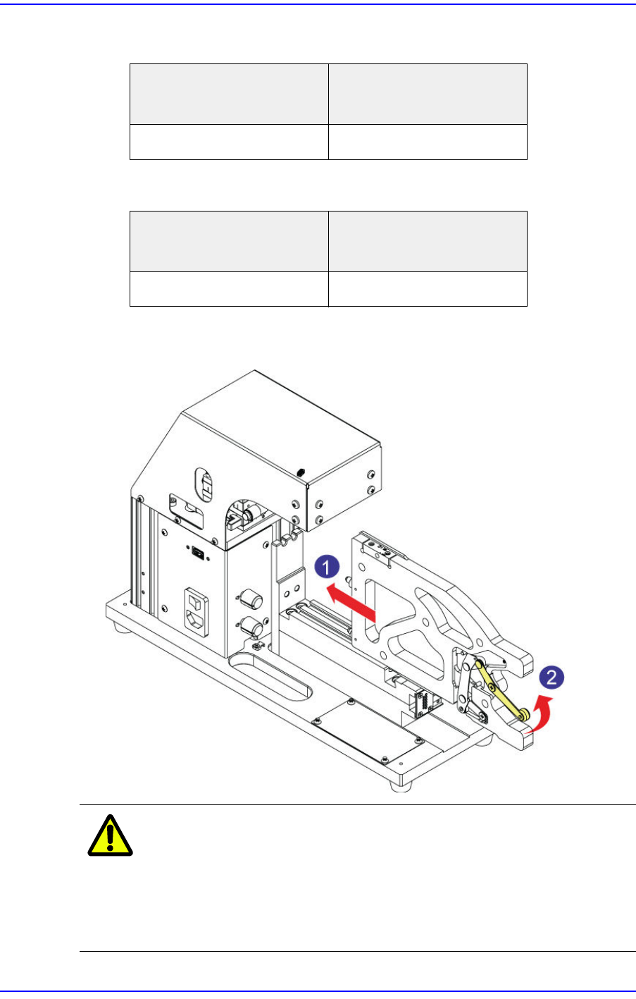
3. After ensuring the master feeder has come into close contact with the front plate of the
calibration jig, push the clamp lever up to fix the master feeder at the feeder base.
Caution
When inserting the master feeder into the feeder slot of the
calibration jig, moving the clamp lever up with a chip or
foreign material being jammed may cause the clamp lever
or link to bend. If the clamp lever or link is bent, replace it
without fail before using the master feeder.
Placement position of the
master feeder
Placement position of the
feeder to be calibrated
Left (#1) Slot Left (#1) Slot
Placement position of the
master feeder
Placement position of the
feeder to be calibrated
Right (#2) Slot Left (#1) Slot