1OPERATION_.pdf - 第100页
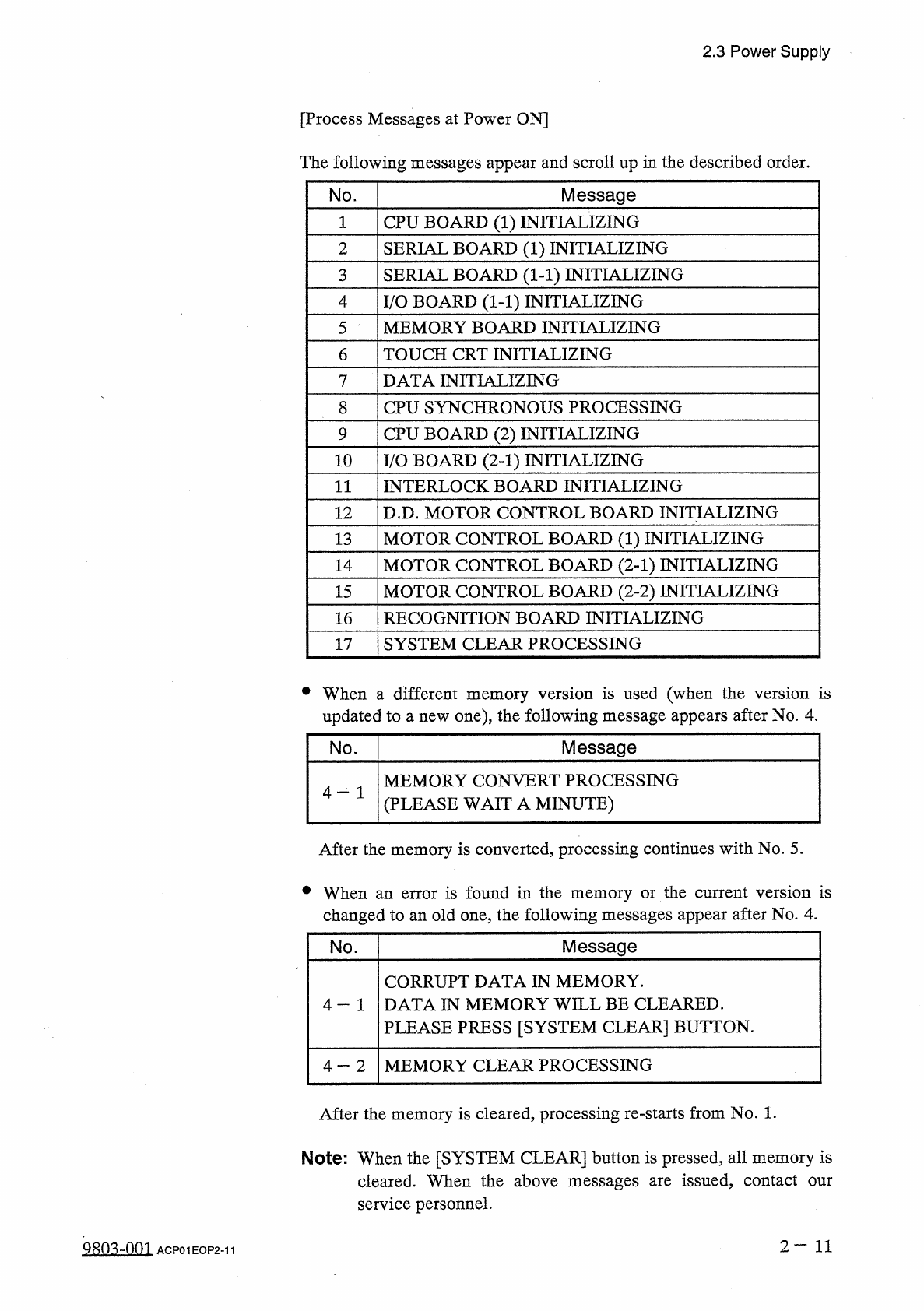
2.3 Power Supply 2.3 . 3 Displays for Initialization at Power ON When the power switch of the machine is turned ON , the program and data are loaded and stored in memory and each P . C . B . is initialized subsequently .…
2.3
Power
Supply
2.3
.
2
Power
Up
the
Machine
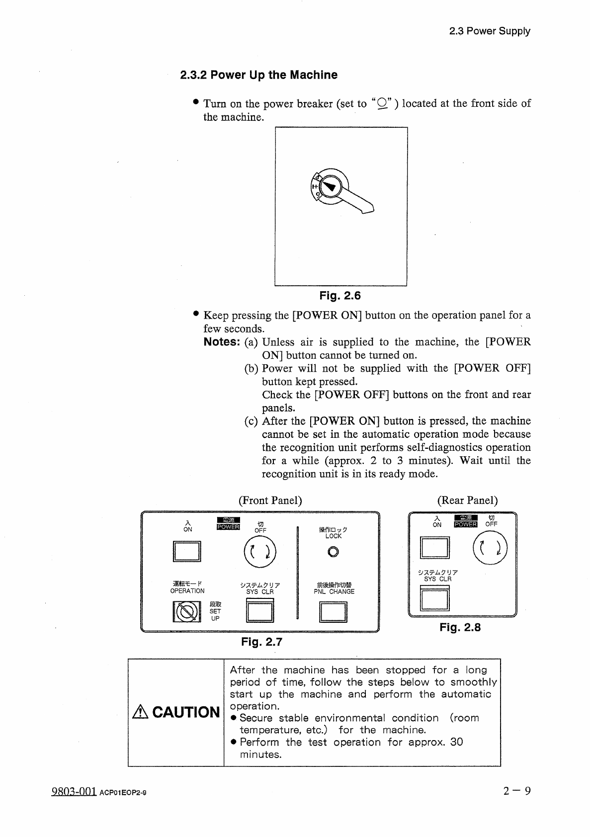
•
Turn
on
the
power
breaker
(
set
to
wOw
)
located
at
the
front
side
of
the
machine
.
Fig
.
2.6
•
Keep
pressing
the
[
POWER
ON
]
button
on
the
operation
panel
for
a
few
seconds
.
Notes
:
(
a
)
Unless
air
is
supplied
to
the
machine
,
the
[
POWER
ON
]
button
cannot
be
turned
on
.
(
b
)
Power
will
not
be
supplied
with
the
[
POWER
OFF
]
button
kept
pressed
.
Check
the
[
POWER
OFF
]
buttons
on
the
front
and
rear
panels
.
(
c
)
After
the
[
POWER
ON
]
button
is
pressed
,
the
machine
cannot
be
set
in
the
automatic
operation
mode
because
the
recognition
unit
performs
self
-
diagnostics
operation
for
a
while
(
approx
.
2
to
3
minutes
)
.
Wait
until
the
recognition
unit
is
in
its
ready
mode
.
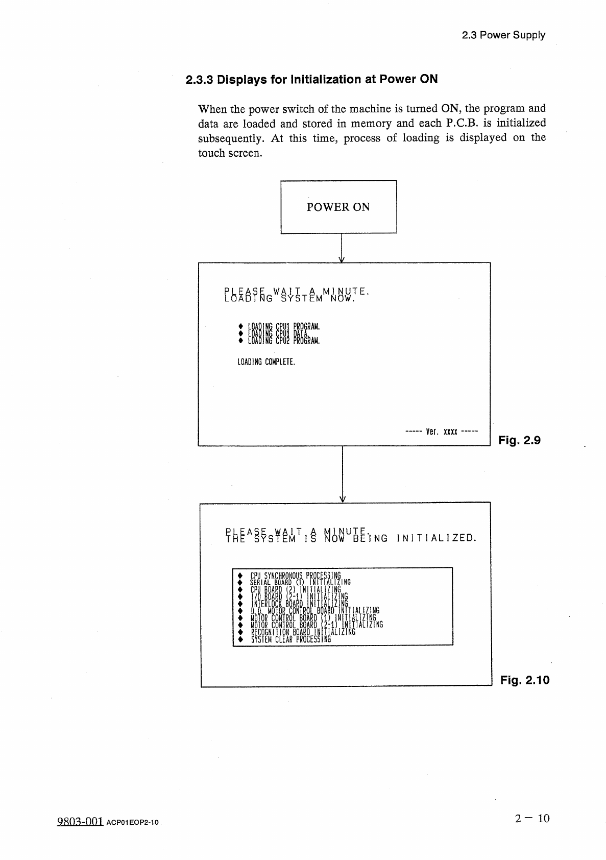
(
Front
Panel
)
(
Rear
Panel
)
/
f
-
ON
切
OFF
'
v
0
LOCK
(
Q
)
O
夕又
x
厶夕
1
J
7
SYS
CLR
運転乇一卜
'
OPERATION
前後操作切替
PNL
CHANGE
夕又亍厶夕
II
7
SYS
CLR
段取
國
SET
UP
Fig
.
2.8
Fig
.
2.7
After
the
machine
has
been
stopped
for
a
long
period
of
time
,
follow
the
steps
below
to
smoothly
start
up
the
machine
and
perform
the
automatic
operation
.
•
Secure
stable
environmental
condition
(
room
temperature
,
etc
.
)
for
the
machine
.
Perform
the
test
operation
for
approx
.
30
minutes
.
A
CAUTION
2
—
9
ACP
01
EOP
2
-
9
2.3
Power
Supply
2.3
.
3
Displays
for
Initialization
at
Power
ON
When
the
power
switch
of
the
machine
is
turned
ON
,
the
program
and
data
are
loaded
and
stored
in
memory
and
each
P
.
C
.
B
.
is
initialized
subsequently
.
At
this
time
,
process
of
loading
is
displayed
on
the
touch
screen
.
POWER
ON
LOADING
COMPLETE
.
ver
.
xxxx
Fig
.
2.9
Y
T
1
i
N
0
WU
5
^
'
]
NG
I N I T I A L
!
ZED
.
CPU
SYNCHRONOUS
PROCESSING
SERIAL
BOARD
(
1
)
INITIALIZING
CPU
BOARD
(
2
)
IN
TIALIZ
N
6
I
/
O
BOARD
(
2
-
1
)
NITIAL
ZIN
6
ONOERMOTOR
CONTROL
1
BOARD
21
SfTIAUZ
1
NG
MOIOR
CONTROL
BOARD
(
1
)
1
'
MOTOR
CONTROL
BOARD
2
-
1
)
RECOGNITION
BOARD
INITIALIZING
SYSTEM
CLEAR
PROCESSING
NiTN
»
Fig
.
2.10
2
—
1 0
98
Q
3
ZQQ
1
ACP
01
EOP
2
-
10
2.3
Power
Supply
[
Process
Messages
at
Power
ON
]
The
following
messages
appear
and
scroll
up
in
the
described
order
.
No
.
Message
CPU
BOARD
(
1
)
INITIALIZING
1
SERIAL
BOARD
(
1
)
INITIALIZING
2
(
1
-
1
)
INITIALIZING
3
SERIAL
BOARD
I
/
O
BOARD
(
1
-
1
)
INITIALIZING
4
MEMORY
BOARD
INITIALIZING
5
TOUCH
CRT
INITIALIZING
6
DATA
INITIALIZING
7
CPU
SYNCHRONOUS
PROCESSING
8
CPU
BOARD
(
2
)
INITIALIZING
9
I
/
O
BOARD
(
2
-
1
)
INITIALIZING
10
INTERLOCK
BOARD
INITIALIZING
11
D
.
D
.
MOTOR
CONTROL
BOARD
INITIALIZING
12
MOTOR
CONTROL
BOARD
(
1
)
INITIALIZING
13
(
2
-
1
)
INITIALIZING
MOTOR
CONTROL
BOARD
14
MOTOR
CONTROL
BOARD
(
2
-
2
)
INITIALIZING
15
RECOGNITION
BOARD
INITIALIZING
16
SYSTEM
CLEAR
PROCESSING
17
•
When
a
different
memory
version
is
used
(
when
the
version
is
updated
to
a
new
one
)
,
the
following
message
appears
after
No
.
4
.
Message
No
.
MEMORY
CONVERT
PROCESSING
(
PLEASE
WAIT
A
MINUTE
)
4
After
the
memory
is
converted
,
processing
continues
with
No
.
5
.
•
When
an
error
is
found
in
the
memory
or
the
current
version
is
changed
to
an
old
one
,
the
following
messages
appear
after
No
.
4
.
Message
No
.
CORRUPT
DATA
IN
MEMORY
.
DATA
IN
MEMORY
WILL
BE
CLEARED
.
PLEASE
PRESS
[
SYSTEM
CLEAR
]
BUTTON
.
4
-
1
MEMORY
CLEAR
PROCESSING
4
-
2
After
the
memory
is
cleared
,
processing
re
-
starts
from
No
.
1
.
Note
:
When
the
[
SYSTEM
CLEAR
]
button
is
pressed
,
all
memory
is
cleared
.
When
the
above
messages
are
issued
,
contact
our
service
personnel
.
2
—
1 1
Qsm
-
nm
ACP
01
EOP
2
-
11