1OPERATION_.pdf - 第79页
1.9 List of Nozzle Types 1.9 List of Nozzle Types The machine is equipped with nozzles designated in the delivery specifications at shipment . Remarks Part No . 、 Part Name ( a ) ( b ) Nozzle Type Applicable Components (…
1.8
Placement
Head
Section
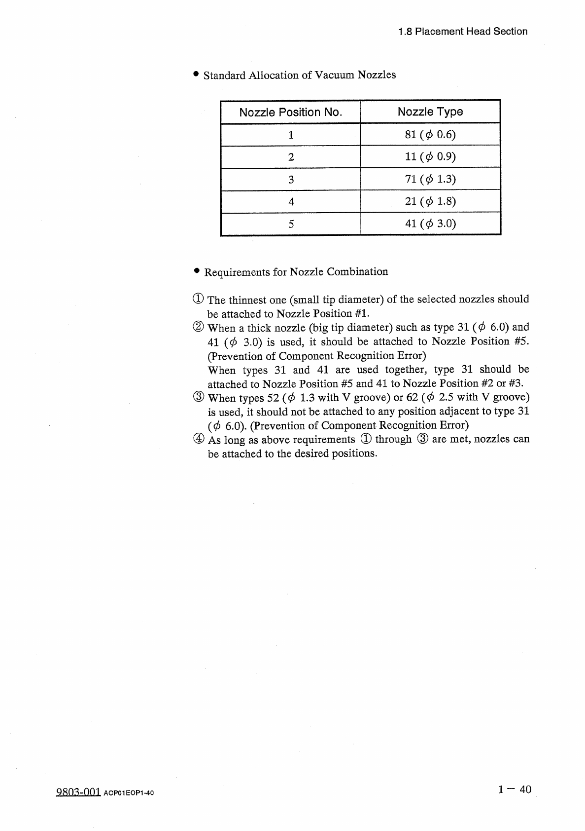
•
Standard
Allocation
of
Vacuum
Nozzles
Nozzle
Position
No
.
Nozzle
Type
81
(
0
0.6
)
11
(
0
0.9
)
2
71
(
0
1.3
)
3
21
(
0
1.8
)
4
41
(
0
3.0
)
5
•
Requirements
for
Nozzle
Combination
①
The
thinnest
one
(
small
tip
diameter
)
of
the
selected
nozzles
should
be
attached
to
Nozzle
Position
#
1
.
②
When
a
thick
nozzle
(
big
tip
diameter
)
such
as
type
31
(
0
6.0
)
and
41
(
0
3.0
)
is
used
,
it
should
be
attached
to
Nozzle
Position
#
5
.
(
Prevention
of
Component
Recognition
Error
)
When
types
31
and
41
attached
to
Nozzle
Position
#
5
and
41
to
Nozzle
Position
#
2
or
#
3
.
③
When
types
52
(
0
1.3
with
V
groove
)
or
62
(
0
2.5
with
V
groove
)
is
used
,
it
should
not
be
attached
to
any
position
adjacent
to
type
31
(
0
6.0
)
.
(
Prevention
of
Component
Recognition
Error
)
④
As
long
as
above
requirements
®
through
③
are
met
,
nozzles
be
attached
to
the
desired
positions
.
used
together
,
type
31
should
be
are
can
1
—
40
9803
-
001
ACP
01
EOP
1
-
40
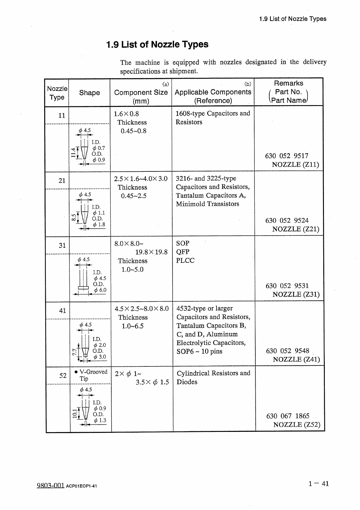
1.9
List
of
Nozzle
Types
1.9
List
of
Nozzle
Types
The
machine
is
equipped
with
nozzles
designated
in
the
delivery
specifications
at
shipment
.
Remarks
Part
No
.
、
Part
Name
(
a
)
(
b
)
Nozzle
Type
Applicable
Components
(
Reference
)
Component
Size
Shape
(
mm
)
1608
-
type
Capacitors
and
Resistors
1.6
X
0.8
Thickness
0.45
-
0.8
11
(
j
)
4.5
I
.
D
.
0
0.7
O
.
D
.
630
052
9517
NOZZLE
(
Zll
)
0
0.9
3216
-
and
3225
-
type
Capacitors
and
Resistors
,
Tantalum
Capacitors
A
,
Minimold
Transistors
2.5
X
1.6
4.0
X
3.0
Thickness
0.45
2.5
21
0
4.5
I
.
D
.
(
p
1.1
O
.
D
.
630
052
9524
NOZZLE
(
Z
21
)
0
1.8
SOP
8.0
X
8.0
31
19.8
X
19.8
QFP
0
4.5
PLCC
Thickness
1.0
5.0
I
I
.
D
.
I
0
4.5
il
O
.
D
.
•
彡
6 . 0
630
052
9531
NOZZLE
(
Z
31
)
4532
-
type
or
larger
Capacitors
and
Resistors
Tantalum
Capacitors
B
C
and
D
Aluminum
Electrolytic
Capacitors
,
SOP
6
10
pins
4.5
X
2.5
8.0
X
8.0
Thickness
1.0
6.5
41
必
4.5
I
.
D
.
0
2.0
O
.
D
.
630
052
9548
NOZZLE
(
Z
41
)
^
(
/
>
3.0
•
V
-
Grooved
2
X
0
1
Cylindrical
Resistors
and
Diodes
52
Tip
3.5
X
0
1.5
0
4.5
I
.
D
.
0
0.9
O
.
D
.
630
067
1865
NOZZLE
(
Z
52
)
0
1.3
1
一
41
2803
=
003
ACP
01
EOP
141
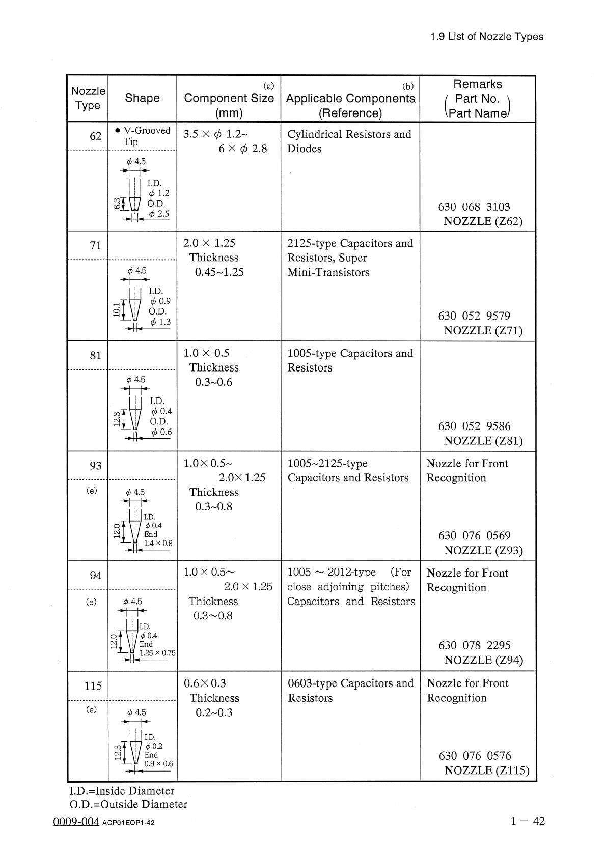
1.9
List
of
Nozzle
Types
Remarks
Part
No
.
、
Part
Name
/
(
a
)
(
b
)
Nozzle
Type
Shape
Component
Size
Applicable
Components
(
Reference
)
(
mm
)
•
V
-
Grooved
3.5
X
0
1.2
'
Cylindrical
Resistors
and
Diodes
62
Tip
6
X
0
2.8
0
4.5
I
.
D
.
(
j
)
1.2
謂
O
.
D
.
630
068
3103
NOZZLE
(
Z
62
)
(
j
)
2.5
2.0
X
1.25
Thickness
0.45
1.25
2125
-
type
Capacitors
and
Resistors
,
Super
Mini
-
Transistors
71
0
45
I
.
D
.
0
0.9
O
.
D
.
630
052
9579
NOZZLE
(
Z
71
)
(
f
>
1.3
1.0
X
0.5
Thickness
0.3
0.6
1005
-
type
Capacitors
and
Resistors
81
0
0.4
O
.
D
.
630
052
9586
NOZZLE
(
Z
81
)
^
0.6
1.0
X
0.5
-
1005
2125
-
type
Capacitors
and
Resistors
Nozzle
for
Front
Recognition
93
2.0
X
1.25
(
e
)
Thickness
0
_
3
0.8
0
4.5
I
.
D
.
0
0.4
End
630
076
0569
NOZZLE
(
Z
93
)
1.4
x
0.9
4
1005
2012
-
type
(
For
close
adjoining
pitches
)
Capacitors
and
Resistors
1.0
x
0.5
Nozzle
for
Front
Recognition
94
2.0
x
1.25
Thickness
0.3
0.8
0
4.5
(
e
)
I
.
D
.
彡
0.4
End
630
078
2295
NOZZLE
(
Z
94
)
1.25
x
0.75
0.6
X
0.3
Thickness
0.2
0.3
0603
-
type
Capacitors
and
Resistors
Nozzle
for
Front
Recognition
115
(
e
)
彡
45
I
.
D
.
彡
0.2
630
076
0576
NOZZLE
(
Z
115
)
End
0.9
x
0.6
I
.
D
.
=
Inside
Diameter
O
.
D
.
=
Outside
Diameter
0009
-
004
1
-
42
ACP
01
EOP
1
-
42