1OPERATION_.pdf - 第285页
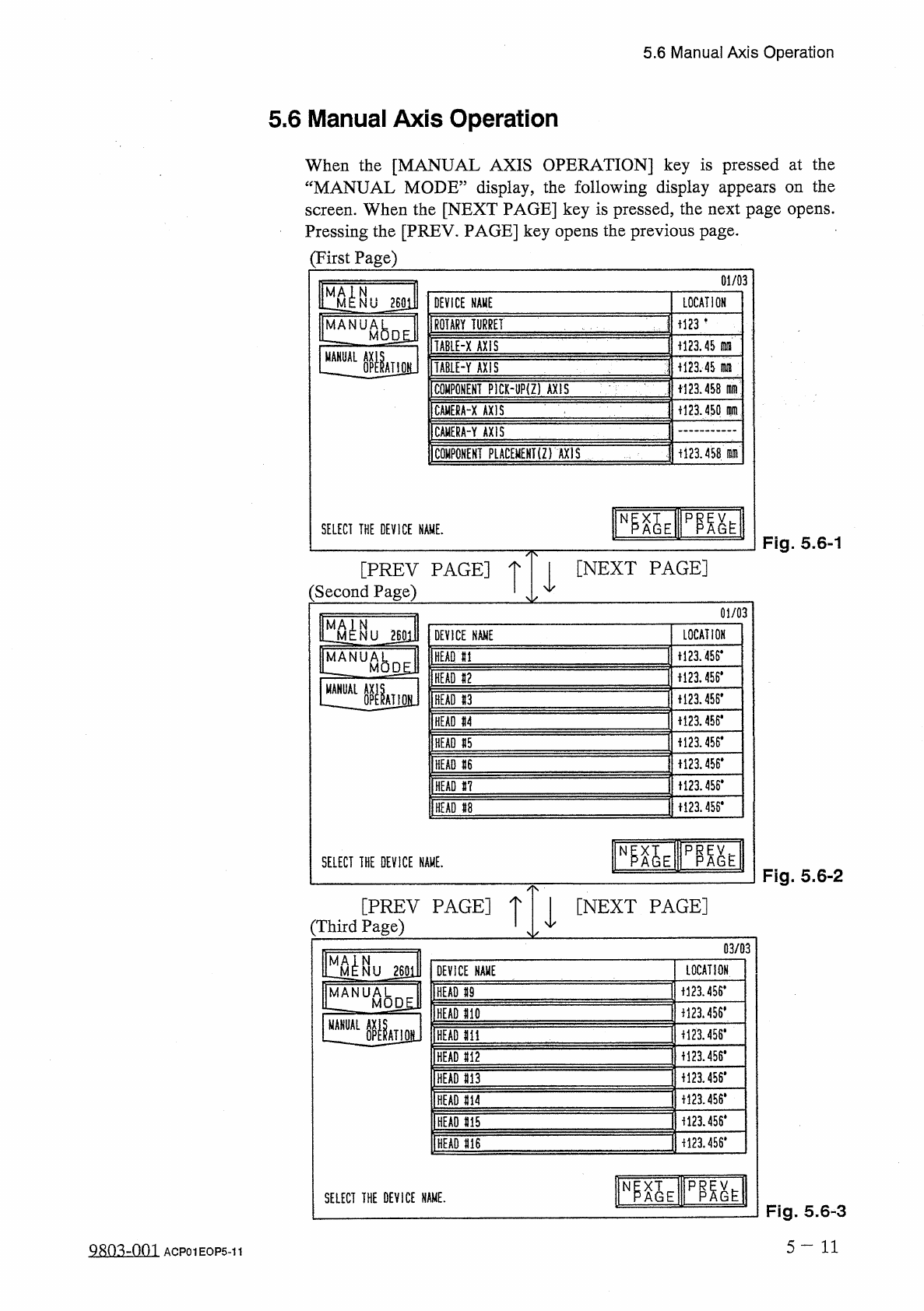
5.6 Manual Axis Operation 5.6 Manual Axis Operation When the [ MANUAL AXIS OPERATION ] key is pressed at the “ MANUAL MODE ” display , the following display appears on the screen . When the [ NEXT PAGE ] key is pressed ,…
5.5
Manual
Subsystem
Operation
⑦
[
HEAD
#
1
VACUUM
VALVE
]
,
[
HEAD
#
16
VACUUM
VALVE
]
The
vacuum
valves
of
head
#
s
1
~
16
are
turned
ON
or
OFF
.
ON
:
Vacuum
is
shut
off
.
OFF
:
Vacuum
is
supplied
.
⑧
[
INPUT
CONVEYOR
(
+
)
]
,
[
INPUT
CONVEYOR
㈠
]
The
input
conveyor
is
rotated
in
the
normal
or
reverse
direction
.
⑨
[
INPUT
BUFFER
CONVEYOR
(
+
)
]
The
input
buffer
conveyor
is
rotated
in
the
normal
direction
.
⑩
[
INPUT
BUFFER
CONVEYOR
P
.
C
.
B
.
STOP
]
The
input
buffer
conveyor
stopper
is
turned
ON
or
OFF
.
⑪
[
OUTPUT
CONVEYOR
(
+
)
]
,
[
OUTPUT
CONVEYOR
(
—
)
]
The
output
conveyor
is
rotated
in
the
normal
or
reverse
direction
.
⑫
[
OUTPUT
CONVEYOR
P
.
C
.
B
.
STOP
]
The
output
conveyor
stopper
is
turned
ON
or
OFF
.
•
Select
the
device
to
be
moved
manually
and
press
the
[
MOVE
]
button
.
•
When
the
rotary
turret
or
the
P
.
C
.
B
.
transfer
is
selected
,
1
-
cycle
or
1
-
step
operation
of
the
turret
or
the
transfer
is
performed
every
time
the
[
MOVE
]
button
is
pressed
.
After
1
-
cycle
or
1
-
step
operation
,
the
selected
device
stops
.
•
When
each
stopper
or
head
vacuum
valve
is
selected
,
the
selected
device
is
turned
ON
or
OFF
every
time
the
[
MOVE
]
button
is
pressed
.
5
—
10
Q
廳
-
om
ACP
01
EOP
5
-
10
5.6
Manual
Axis
Operation
5.6
Manual
Axis
Operation
When
the
[
MANUAL
AXIS
OPERATION
]
key
is
pressed
at
the
“
MANUAL
MODE
”
display
,
the
following
display
appears
on
the
screen
.
When
the
[
NEXT
PAGE
]
key
is
pressed
,
the
next
page
opens
.
Pressing
the
[
PREV
.
PAGE
]
key
opens
the
previous
page
.
(
First
Page
)
01
/
03
DEVICE
NAME
LOCATION
m
-
ROTARY
TURRET
TABIE
-
X
AXIS
i
!
23.45
fllil
_
AL
iU
H
23
.
45
fWIl
TAB
1
E
-
Y
AXIS
COMPONENT
PICK
-
UP
(
Z
)
AXIS
+
123.458
dim
+
123.450
m
CAMERA
-
X
AXIS
CAMERA
-
Y
AXIS
COMPONENT
PLACEMEHT
(
Z
)
AXIS
i
123.458
.
m
SELECT
THE
DEVICE
NAME
.
Fig
.
5.6
-
1
[
NEXT
PAGE
]
[
PREV
PAGE
]
:
Second
Page
)
01
/
03
LOCATION
NU
260
H
DEVICE
NAME
1121
456
*
MANUA
HEAD
HI
M
HEAD
11
ii
23.456
#
HEAD
#
3
+
123.456
*
HEAD
«
4
H
23
.
W
HEAD
15
1123
.
456
*
HEAD
«
6
十
121455
.
HEAD
#
7
+
123.456
*
HEAD
U
SELECT
THE
DEVICE
NAME
,
Fig
.
5.6
-
2
[
PREV
PAGE
]
[
NEXT
PAGE
]
(
Third
Page
)
03
/
03
m
:
-
LOCATION
DEVICE
NAME
1123.4
S
6
*
HEAD
59
MANUAL
U
_
M
0
D
£
J
1
HEAD
110
MANUAL
f
123.456
*
HEAD
m
1123.456
#
HEAD
M
2
f
!
23.456
#
HEAD
m
M
23.456
.
HEAD
M
1123.456
*
HEAD
m
M
23.456
*
HEAD
m
臨
E
PP
.
N
SELECT
THE
DEVICE
NAME
.
Fig
.
5.6
-
3
5
-
11
ACP
01
EOP
5
-
11
5.6
Manual
Axis
Operation
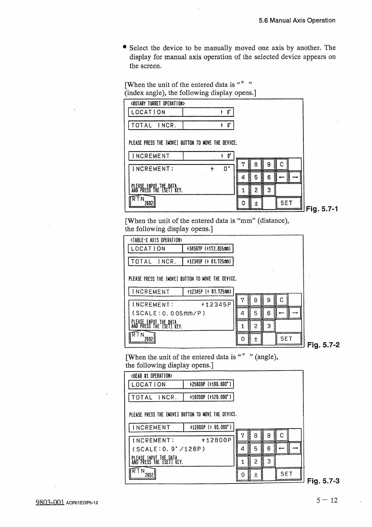
•
Select
the
device
to
be
manually
moved
one
axis
by
another
.
The
display
for
manual
axis
operation
of
the
selected
device
appears
on
the
screen
.
[
When
the
unit
of
the
entered
data
is
“
0
’
’
(
index
angle
)
,
the
following
display
opens
.
]
〈
ROTARY
TURRET
OPERATION
〉
LOCATION
+
0
.
TOTAL
iNCR
.
t
0
#
PLEASE
PRESS
THE
[
MOVE
]
BUTTON
TO
MOVE
THE
DEVICE
.
t
0
*
INCREMENT
9
C
7
8
INCREMENT
:
0
*
5
6
4
3
2
1
fRTN
2602
SET
0
土
Fig
.
5.7
-
1
[
When
the
unit
of
the
entered
data
is
“
mm
”
(
distance
)
,
the
following
display
opens
.
]
<
IABLE
-
X
AXIS
OPERATION
)
LOCATION
十
34567
P
(
t
!
72.835
mm
)
TOTAL
l
NCR
.
+
12345
F
(
t
61725
mD
)
PLEASE
PRESS
THE
IMOVE
]
BUTTON
TO
MOVE
THE
DEVICE
.
INCREMENT
H
2345
P
(
t
61.725
刪
I
C
7
8
9
INCREMENT
:
(
SCALE
:
0
.
0
05
mm
/
P
)
罪霍
十
12345
P
5
6
4
3
2
1
Y
.
pTN
2602
SET
O
土
Fig
.
5.7
-
2
[
When
the
unit
of
the
entered
data
is
“
°
”
(
angle
)
,
the
following
display
opens
.
]
<
HEAD
li
OPERATION
)
音
25600
P
(
t
!
80.000
,
)
LOCATION
+
19200
P
(
H
20.000
*
)
TOTAL
I
NCR
.
PLEASE
PRESS
THE
[
MOVE
]
BUTTON
TO
HOVE
THE
DEVICE
.
f
!
2800
P
(
t
90
.
000
*
)
1
NCREMENT
C
7
8
9
十
12800
P
INCREMENT
:
(
SCALE
:
0
.
9
m
/
128
P
)
5
6
4
TA
2
3
KEY
.
1
rvi
SET
O
土
Fig
.
5.7
-
3
5
一
12
QRO
^
-
nm
ACP
01
EOP
5
-
12