1OPERATION_.pdf - 第88页
◎ h _ _ r 1 Page 2 - 1 2.1 Hierarchical Structure of Operation Displays - 2.1 . 1 “ MAIN MENU ” Display 2.1 . 2 Hierarchical Structure of Operation Menus 2.1 . 3 Hierarchical Displays 2.1 . 4 Touch Screen Keys 2.2 Notes …
1.12
Recognition
Monitor
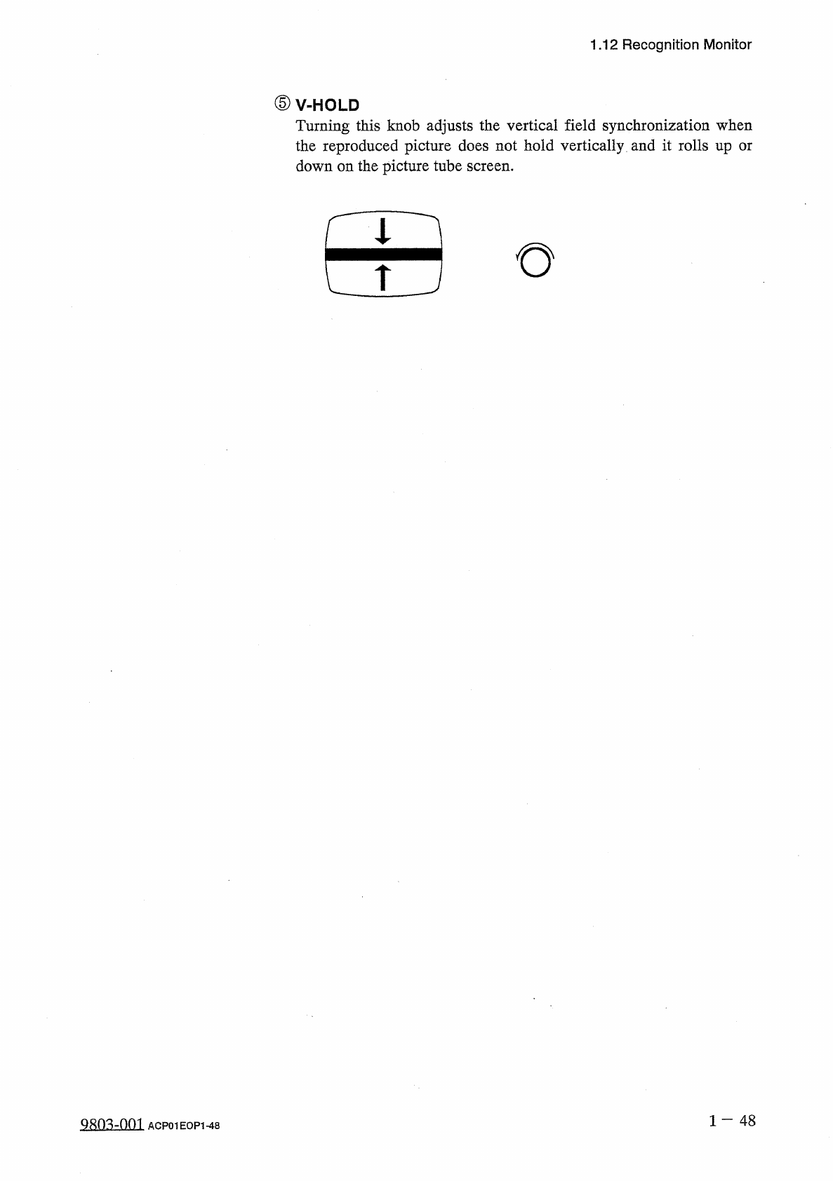
⑤
V
-
HOLD
Turning
this
knob
adjusts
the
vertical
field
synchronization
when
the
reproduced
picture
does
not
hold
vertically
and
it
rolls
up
or
down
on
the
picture
tube
screen
.
田
1
—
48
ACP
01
EOP
1
-
48
◎
h
_
_
r
1
Page
2
-
1
2.1
Hierarchical
Structure
of
Operation
Displays
-
2.1
.
1
“
MAIN
MENU
”
Display
2.1
.
2
Hierarchical
Structure
of
Operation
Menus
2.1
.
3
Hierarchical
Displays
2.1
.
4
Touch
Screen
Keys
2.2
Notes
on
Handling
Touch
Screen
2.3
Power
Supply
2.3
,
1
Confirmation
of
Correct
Power
Supply
and
Air
Pressure
2
-
1
2
-
3
2
-
4
2
-
5
2
-
6
2
-
8
2
-
8
2
-
9
2.3
.
2
Power
Up
the
Machine
2.3
.
3
Displays
for
Initialization
at
Power
ON
2.4
Thorough
Procedures
(
from
starting
through
ending
operations
including
preparation
)
for
Automatic
Operation
(
Component
Placement
)
2.5
Preparation
of
Pattern
Program
Data
2.5
.
1
Creation
of
Current
Pattern
Program
Data
•
-
2.5
.
2
Registration
(
Storage
in
Memory
)
of
Current
Pattern
Program
Data
-
2
-
10
2
-
13
2
-
15
2
-
15
2
-
15
2
-
17
2.6
Program
Change
2.6
.
1
Adjustment
of
P
.
C
.
B
.
Transfer
Section
2.6
.
2
Adjustment
of
X
/
Y
Table
Section
2.6
.
3
Preparation
of
Tape
Feeders
2.6
.
4
Selection
of
Current
Pattern
Program
(
Program
Change
)
2.6
.
5
All
Data
Clear
Operation
for
Feeder
(
B
)
Offset
2.7
Verification
of
Current
Pattern
Program
Data
2.7
.
1
P
.
E
.
C
.
Recognition
Test
2.7
.
2
X
/
Y
Table
Test
at
P
.
E
.
C
.
Position
2.7
.
3
Operation
for
Confirmation
2.7
.
4
Actual
Component
Placement
Test
2
-
17
2
-
18
2
-
24
2
-
25
2
-
26
2
-
27
2
-
27
2
-
28
2
-
29
2
-
29
0003
-
003
ACP
01
EOPCC
2
Page
2
-
30
2.8
Setting
of
Operation
Mode
2.8
.
1
Automatic
Feeder
Axis
Adjustment
Mode
•
2.8
.
2
Overall
Tact
Time
Reduction
2.8
.
3
Shortage
of
Component
Detection
Mode
•
…
2.8
.
4
Alternate
Mode
2.8
.
5
Recovery
Mode
2.8
.
6
Feeder
Carriage
Axis
Mode
2.8
.
7
X
/
Y
Table
Axis
Mode
2.8
.
8
Trash
Box
Fill
Up
Warning
Mode
2.9
Starting
,
Emergency
Stop
and
Temporary
Stop
(
Pause
)
Operations
for
Automatic
Operation
(
“
PLACE
”
Mode
)
2.9
.
1
General
Start
2
-
30
2
-
30
2
-
30
2
-
30
2
-
30
2
-
30
2
-
30
2
-
30
2
-
31
2
-
31
and
Emergency
Stop
Procedures
2.9
.
2
Temporary
Stop
Procedure
of
Automatic
Operation
(
“
PLACE
”
Mode
)
2
-
33
2
-
33
2.9
.
3
Start
Procedure
from
“
PAUSE
”
Mode
2.9
.
4
Replacement
of
Tape
Feeders
during
Operation
2.10
Interruption
of
Automatic
Operation
(
“
PLACE
”
Mode
)
2.10
.
1
How
to
Interrupt
the
Automatic
Operation
2.10
.
2
Function
of
[
SYS
CLR
]
Button
2.11
Reset
and
Start
Procedure
from
Emergency
Stop
(
Automatic
Operation
(
“
PLACE
”
Mode
))
2.11
.
1
Cause
and
Symptom
of
Emergency
Stop
2.11
.
2
Reset
and
Start
Procedure
from
Emergency
Stop
(
Automatic
Operation
(
“
PLACE
”
Mode
}
)
…
.
2.12
Stopping
Automatic
Operation
(
“
PLACE
”
Mode
)
2.12
.
1
General
Stop
Procedure
2.12
.
2
Automatic
Stop
Procedure
2.12
.
3
Emergency
Stop
Procedure
2
-
34
2
-
36
2
-
36
2
-
36
2
-
38
2
-
38
2
-
38
2
-
41
2
-
41
2
-
41
2
-
41
9803
-
001
ACP
01
EOPCC
2