1OPERATION_.pdf - 第216页
RJCOMPOHENT ID c rpirinYprii TAPE ENO F D R . [ SCREENS M 3 N ( COMPONENT CARRIAGE DATA EDIT 〉 4.7 RECOVERY OPN . TEACHING OPN . 4.7 . 3 Modification of Component Carriage Data ( Simplified Packaging Direction Change Fun…
4.7
RECOVERY
OPN
.
TEACHING
OPN
.
4.7
.
2
COMPONENT
LIBRARY
EDIT
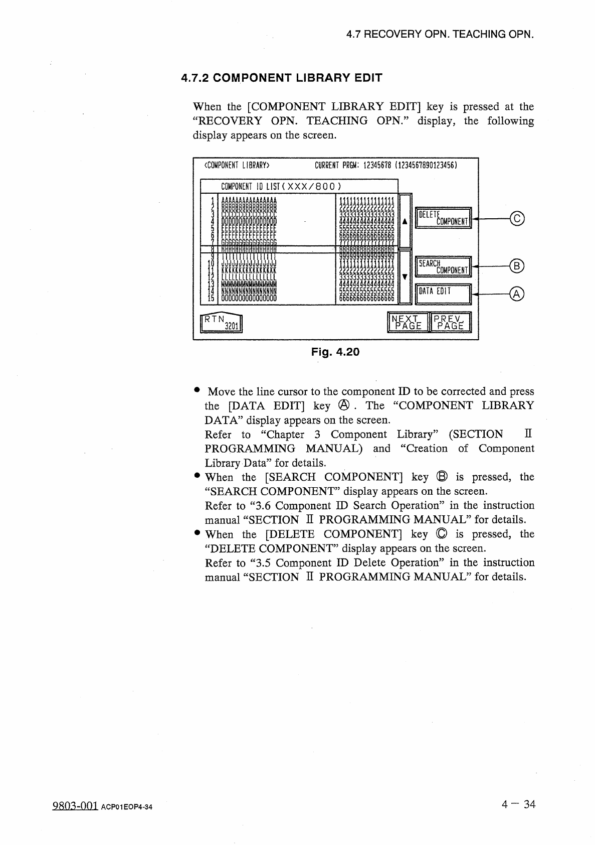
When
the
[
COMPONENT
LIBRARY
EDIT
]
key
is
pressed
at
the
“
RECOVERY
OPN
.
TEACHING
OPN
.
”
display
,
the
following
display
appears
on
the
screen
.
CURRENT
PRGM
:
12345678
(
1234567890123456
)
〈
COMPONENT
LIBRARY
)
COMPONENT
10
LIST
(
X X X
/
8 0 0
)
AAAAAAA
AAAAAAAA
I
IIIIII
1111
L
5555555555555555
DELE
了
33333
4
0
MF
0
NENT
5
FFFFFFF
FFFFFFFF
6686666666666666
llllil
niiiTriiirifiif
<
D
10
KKKKKUKKXKKKKKK
LLLLLLLLIULLLLL
NNNNN
^
fiNNNNNNNNN
0000000000000000
SEARCH
II
445555555555
|
|
66666666666666
1
COMPONENT
13
DATA
EDIT
55
14
15
66
WE
f
^
l
NPEAXGTE
Fig
.
4.20
•
Move
the
line
cursor
to
the
component
ID
to
be
corrected
and
press
the
[
DATA
EDIT
]
key
@
•
The
“
COMPONENT
LIBRARY
DATA
”
display
appears
on
the
screen
.
Refer
to
“
Chapter
3
Component
Library
”
(
SECTION
PROGRAMMING
MANUAL
)
and
“
Creation
of
Component
Library
Data
”
for
details
.
•
When
the
[
SEARCH
COMPONENT
]
key
®
is
pressed
,
the
“
SEARCH
COMPONENT
”
display
appears
on
the
screen
.
Refer
to
“
3.6
Component
ID
Search
Operation
”
in
the
instruction
manual
“
SECTION
H
PROGRAMMING
MANUAL
”
for
details
.
•
When
the
[
DELETE
COMPONENT
]
key
©
is
pressed
,
the
“
DELETE
COMPONENT
”
display
appears
on
the
screen
.
Refer
to
“
3.5
Component
ID
Delete
Operation
”
in
the
instruction
manual
“
SECTION
H
PROGRAMMING
MANUAL
”
for
details
.
n
4
-
34
Q
^
o
^
-
nm
ACP
01
EOP
4
-
34
RJCOMPOHENT
ID
c
rpirinYprii
TAPE
ENO
FDR
.
[
SCREENS
M
3
N
(
COMPONENT
CARRIAGE
DATA
EDIT
〉
4.7
RECOVERY
OPN
.
TEACHING
OPN
.
4.7
.
3
Modification
of
Component
Carriage
Data
(
Simplified
Packaging
Direction
Change
Function
)
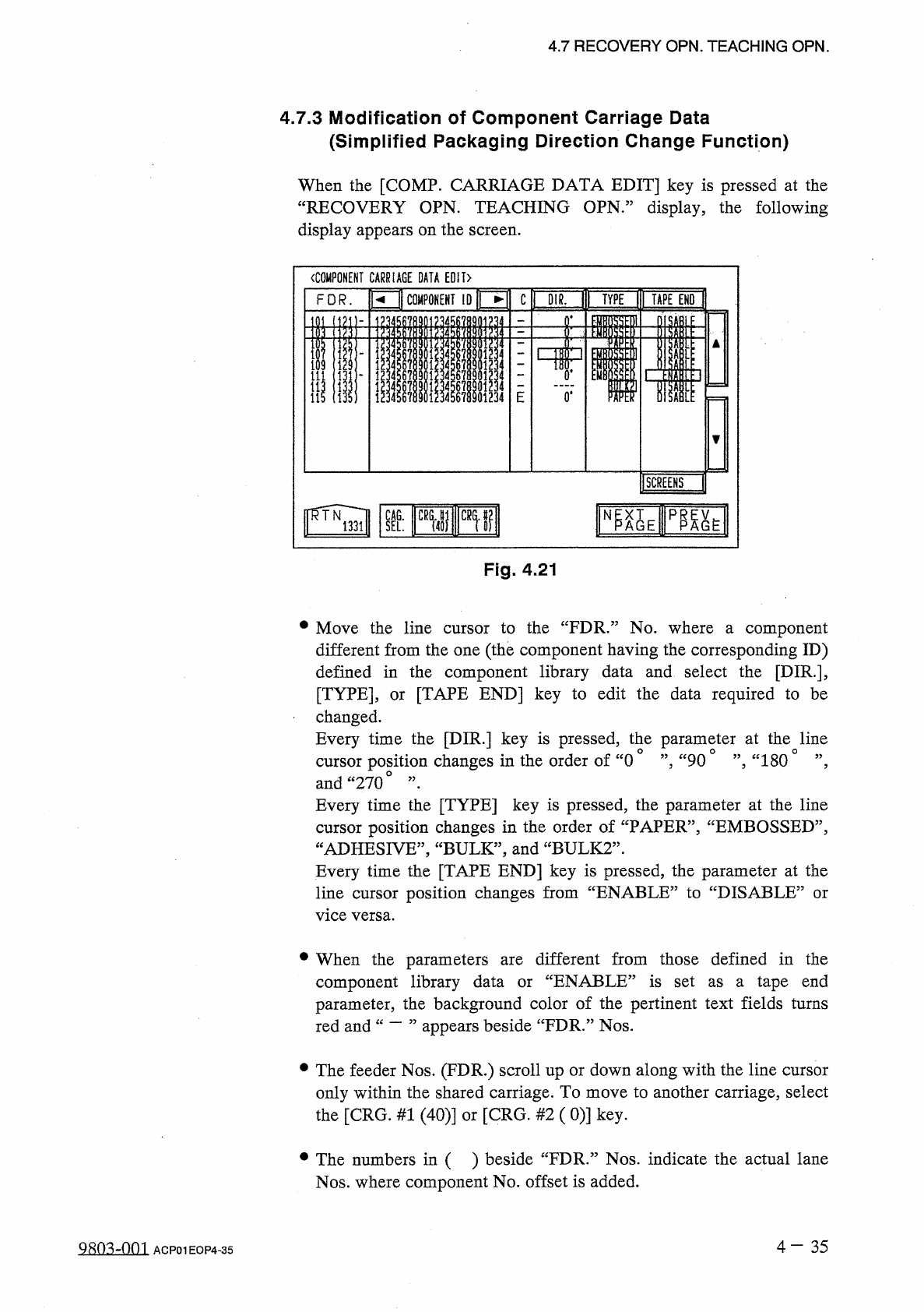
When
the
[
COMP
.
CARRIAGE
DATA
EDIT
]
key
is
pressed
at
the
“
RECOVERY
OPN
.
TEACHING
OPN
,
”
display
,
the
following
display
appears
on
the
screen
.
Fig
.
4.21
•
Move
the
line
cursor
to
the
“
FDR
”
No
.
where
a
component
different
from
the
one
(
the
component
having
the
corresponding
ID
)
defined
in
the
component
library
data
and
select
the
[
DIR
.
]
,
[
TYPE
]
,
or
[
TAPE
END
]
key
to
edit
the
data
required
to
be
changed
.
Every
time
the
[
DIR
.
]
key
is
pressed
,
the
parameter
at
the
line
cursor
position
changes
in
the
order
of
“
0
°
”
,
“
90
°
”
,
“
1800
”
,
and
“
270
o
,,
•
Every
time
the
[
TYPE
]
key
is
pressed
,
the
parameter
at
the
line
cursor
position
changes
in
the
order
of
“
PAPER
”
,
“
EMBOSSED
”
,
“
ADHESIVE
,
,
,
“
BULK
,
,
,
and
“
BULK
2
”
.
Every
time
the
[
TAPE
END
]
key
is
pressed
,
the
parameter
at
the
line
cursor
position
changes
from
“
ENABLE
”
to
“
DISABLE
5
vice
versa
.
or
•
When
the
parameters
component
library
data
parameter
,
the
background
color
of
the
pertinent
text
fields
turns
appears
beside
“
FDR
.
”
Nos
.
different
from
those
defined
in
the
“
ENABLE
”
is
set
as
a
tape
end
are
or
red
and
•
The
feeder
Nos
.
(
FDR
.
)
scroll
up
or
down
along
with
the
line
cursor
only
within
the
shared
carriage
.
To
move
to
another
carriage
,
select
the
[
CRG
.
#
1
(
40
)
]
or
[
CRG
.
#
2
(
0
)
]
key
.
•
The
numbers
in
( )
beside
“
FDR
.
”
Nos
.
indicate
the
actual
lane
Nos
.
where
component
No
.
offset
is
added
.
4
-
35
9803
^
001
ACP
01
EOP
4
-
35
is
i
i
llSCREENS
C
lTHKNS
.
t
]
|
VEOr
|
)
THKHiCHKn
COMPONENT
ID
FDR
.
〈
COMPONENT
CARRIAGE
DATA
EDIT
>
4.7
RECOVERY
OPN
.
TEACHING
OPN
.
•
When
“
BULK
2
”
is
set
in
the
“
TYPE
”
text
field
,
“
”
appears
in
the
“
DIR
”
text
field
,
indicating
that
the
direction
cannot
be
changed
.
•
When
“
BULK
2
”
is
set
in
the
“
TYPE
”
text
field
,
the
tape
end
detection
function
cannot
be
activated
.
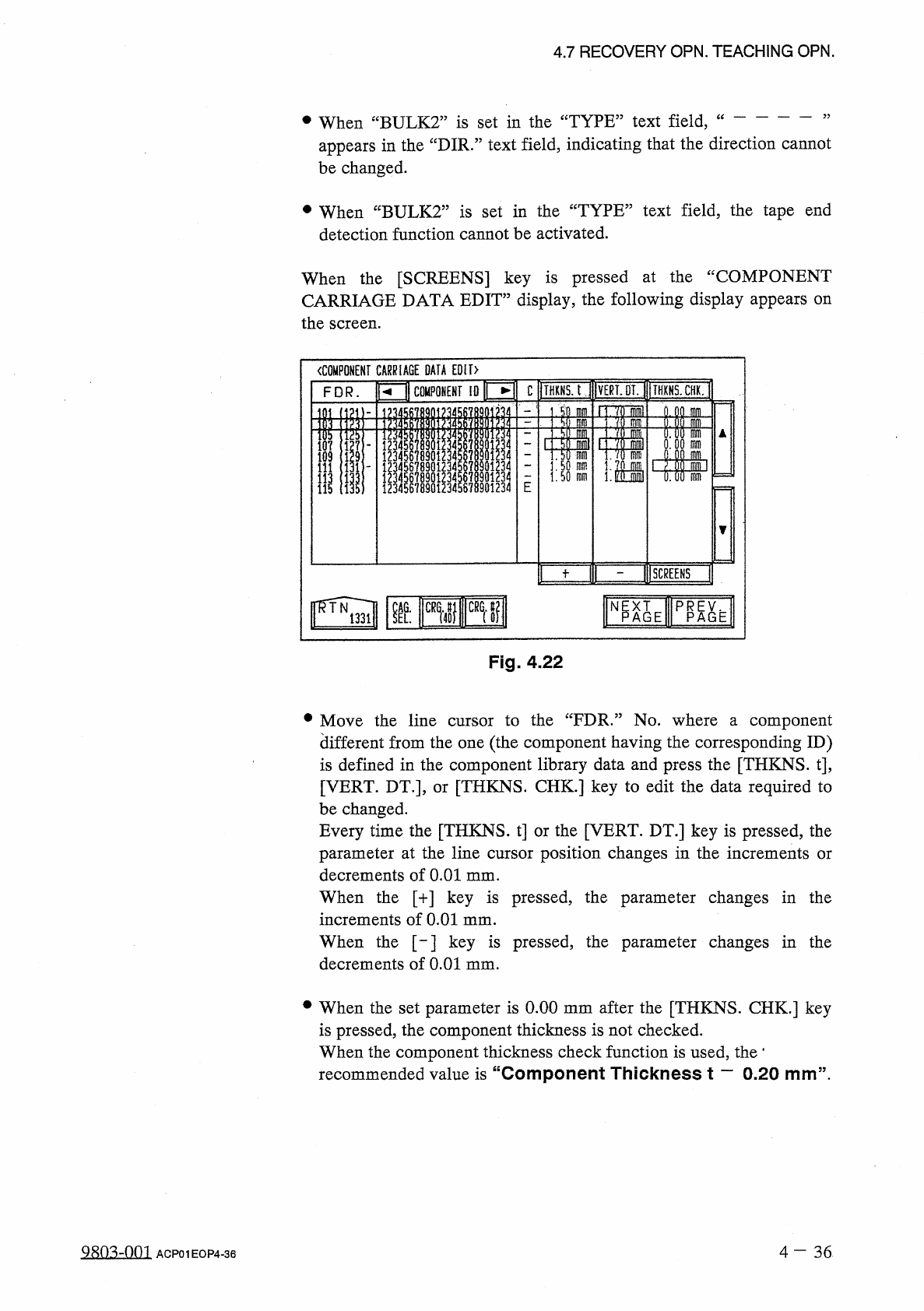
When
the
[
SCREENS
]
key
is
pressed
at
the
“
COMPONENT
CARRIAGE
DATA
EDIT
”
display
,
the
following
display
appears
on
the
screen
.
Fig
.
4.22
•
Move
the
line
cursor
to
the
“
FDR
.
”
No
.
where
a
component
different
from
the
one
(
the
component
having
the
corresponding
ID
)
is
defined
in
the
component
library
data
and
press
the
[
THKNS
.
t
]
,
[
VERT
.
DT
.
]
,
or
[
THKNS
.
CHK
.
]
key
to
edit
the
data
required
to
be
changed
.
Every
time
the
[
THKNS
.
t
]
or
the
[
VERT
.
DT
.
]
key
is
pressed
,
the
parameter
at
the
line
cursor
position
changes
in
the
increments
or
decrements
of
0.01
mm
.
When
the
[
+
]
key
is
pressed
,
the
parameter
changes
in
the
increments
of
0.01
mm
.
When
the
[
-
]
key
is
pressed
,
the
parameter
changes
in
the
decrements
of
0.01
mm
.
•
When
the
set
parameter
is
0.00
mm
after
the
[
THKNS
.
CHK
.
]
key
is
pressed
,
the
component
thickness
is
not
checked
.
When
the
component
thickness
check
function
is
used
,
the
*
recommended
value
is
“
Component
Thickness
t
一
0.20
mm
”
.
9
sn
^
-
nm
4
-
36
ACP
01
EOP
4
-
36
u
議刪關凰凰
|
1
]
11
)
Mss
刪
nlni
瞧
腿聊
4
/
u
444
30
J
333
Qiolol
i
I
4
L
414
iJT
*
4
i
ooooo
889
SS
RW
666
r
3
rD
5
rD
44444
330
JOJ
3
ot
2
n
/
5
L
2
15710911122