1OPERATION_.pdf - 第46页
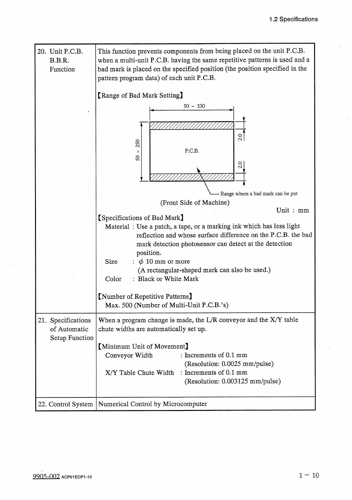
1.2 Specifications This function prevents components from being placed on the unit P . C . B . when a multi - unit P . C . B . having the same repetitive patterns is used and a bad mark is placed on the specified positio…
1.2
Specifications
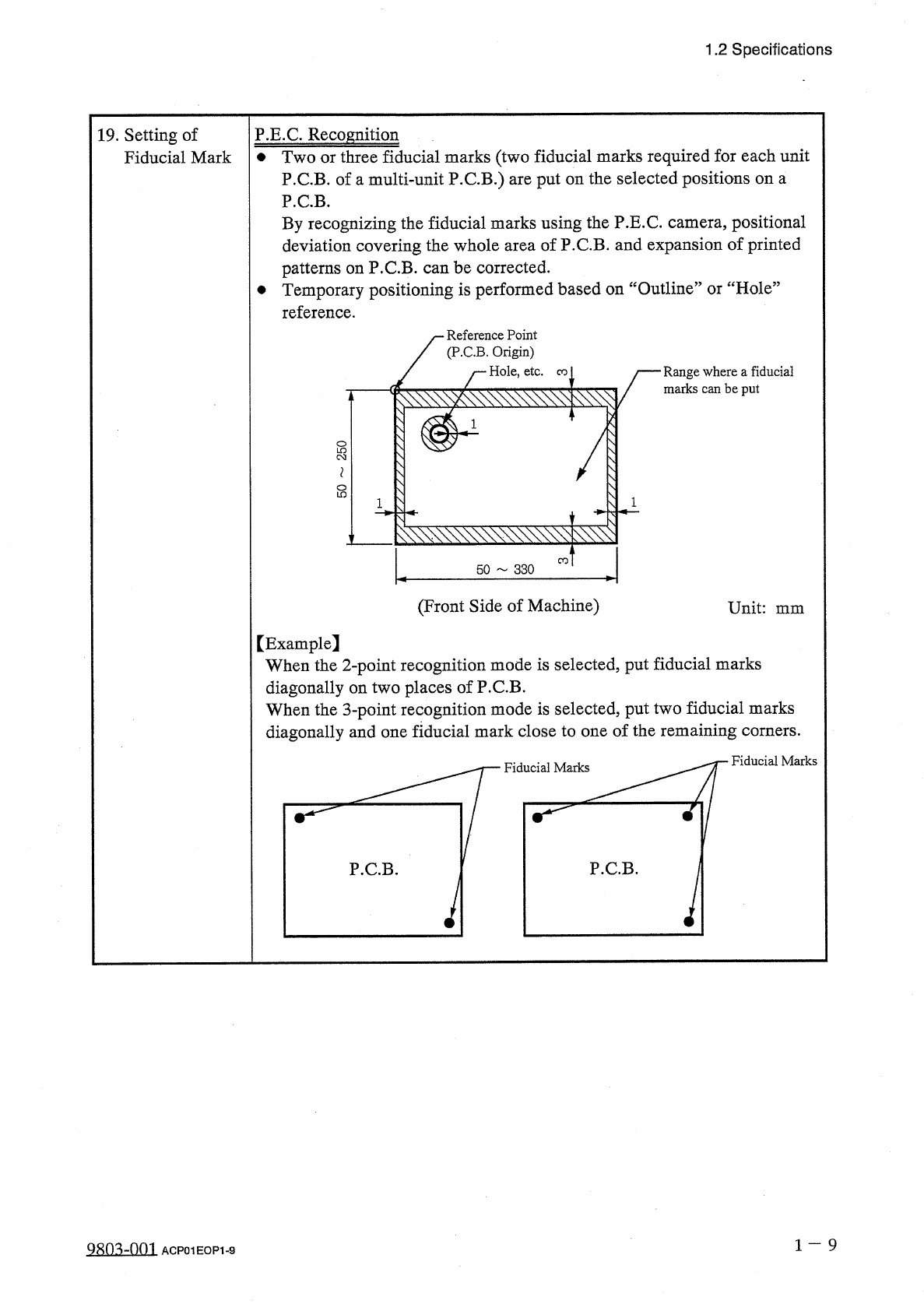
19
.
Setting
of
Fiducial
Mark
P
.
E
.
C
.
Recognition
•
Two
or
three
fiducial
marks
(
two
fiducial
marks
required
for
each
unit
P
.
C
.
B
.
of
a
multi
-
unit
P
.
C
.
B
.
)
are
put
on
the
selected
positions
on
a
P
.
C
.
B
.
By
recognizing
the
fiducial
marks
using
the
P
.
E
.
C
.
camera
,
positional
deviation
covering
the
whole
area
of
P
.
C
.
B
.
and
expansion
of
printed
patterns
on
P
.
C
.
B
.
can
be
corrected
.
•
Temporary
positioning
is
performed
based
on
“
Outline
”
or
“
Hole
”
reference
.
Reference
Point
(
P
.
C
.
B
.
Origin
)
Hole
,
etc
.
Range
where
a
fiducial
marks
can
be
put
co
l
8
CO
50
330
(
Front
Side
of
Machine
)
Unit
:
mm
【
Example
】
When
the
2
-
point
recognition
mode
is
selected
,
put
fiducial
marks
diagonally
on
two
places
of
P
.
C
.
B
.
When
the
3
-
point
recognition
mode
is
selected
,
put
two
fiducial
marks
diagonally
and
one
fiducial
mark
close
to
one
of
the
remaining
corners
.
Fiducial
Marks
Fiducial
Marks
1
一
9
Q
80
^
-
nm
ACP
01
EOP
1
-
9
1.2
Specifications
This
function
prevents
components
from
being
placed
on
the
unit
P
.
C
.
B
.
when
a
multi
-
unit
P
.
C
.
B
.
having
the
same
repetitive
patterns
is
used
and
a
bad
mark
is
placed
on
the
specified
position
(
the
position
specified
in
the
pattern
program
data
)
of
each
unit
P
.
C
.
B
.
20
.
UnitP
.
CB
.
B
.
B
.
R
.
Function
[
Range
of
Bad
Mark
Setting
]
50
330
y
/
/
/
/
/
/
/
/
/
/
/
/
/
/
/
/
/
/
/
/
/
/
/
z
P
.
C
.
B
.
-
A
.
Range
where
a
bad
mark
can
be
put
(
Front
Side
of
Machine
)
Unit
:
mm
[
Specifications
of
Bad
Mark
】
Material
:
Use
a
patch
,
a
tape
,
or
a
marking
ink
which
has
less
light
reflection
and
whose
surface
difference
on
the
P
.
C
.
B
.
the
bad
mark
detection
photosensor
can
detect
at
the
detection
position
.
:
0
10
mm
or
more
(
A
rectangular
-
shaped
mark
can
also
be
used
.
)
:
Black
or
White
Mark
Size
Color
【
Number
of
Repetitive
Patterns
]
Max
.
500
(
Number
of
Multi
-
Unit
P
.
C
.
B
.
’
s
)
21
.
Specifications
of
Automatic
Setup
Function
When
a
program
change
is
made
,
the
L
/
R
conveyor
and
the
X
/
Y
table
chute
widths
are
automatically
set
up
.
[
Minimum
Unit
of
Movement
]
Conveyor
Width
:
Increments
of
0.1
mm
(
Resolution
:
0.0025
mm
/
pulse
)
X
/
Y
Table
Chute
Width
:
Increments
of
0.1
mm
(
Resolution
:
0.003125
mm
/
pulse
)
Numerical
Control
by
Microcomputer
22
.
Control
System
1
-
1 0
9905
-
002
ACPOIEOPI
-
IO
1.2
Specifications
:
Absolute
Command
:
Feeder
Axis
Lane
No
.
Designation
:
Absolute
Command
23
.
Command
System
Table
Movement
Carriage
Movement
Rotation
for
Positioning
Pick
-
Up
Condition
(
including
the
height
control
)
(
Library
System
)
:
Components
Code
Data
Command
(
including
the
height
control
)
(
Library
System
)
:
Components
Code
Data
Command
Placement
Condition
ASCII
Code
24
.
Pattern
Program
Data
Code
According
to
touch
panel
switch
operation
and
the
programming
device
(
option
)
(
Data
reading
from
floppy
disk
)
25
.
Pattern
Program
Data
Input
System
Data
display
on
the
touch
panel
Data
transfer
to
the
programming
device
(
option
)
and
Data
output
by
the
printer
(
option
)
(
Data
saving
on
a
floppy
disk
)
26
.
Pattern
Program
Data
Output
System
Pattern
program
data
editing
is
possible
with
touch
panel
switch
operation
.
27
.
Pattern
Program
Data
Editing
Maximum
Number
of
Steps
:
5
,
000
steps
/
program
Maximum
Memorized
Number
of
Programs
:
24
programs
Note
:
The
above
numbers
may
be
limited
according
to
the
capacity
of
the
pattern
program
.
Consult
our
sales
personnel
for
details
.
28
.
Pattern
Program
Memory
Capacity
Built
-
In
Backup
RAM
Pattern
program
data
can
be
saved
in
the
data
storage
device
of
the
programming
device
(
option
)
.
Pattern
program
data
can
be
saved
on
a
floppy
disk
.
29
.
Pattern
Program
Data
Saving
30
.
Output
System
of
Management
Data
Display
of
the
touch
panel
management
data
,
output
to
the
programming
device
(
option
)
or
the
printer
.
31
.
Power
Supply
200
±
20
V
AC
,
3
-
phase
,
50
/
60
Hz
Connected
to
the
power
supply
unit
(
3
-
phase
4
-
wire
system
)
(
One
of
the
four
wires
is
used
as
a
ground
wire
.
)
32
.
Maximum
Power
Consumption
Approx
.
7
kVA
039
0.69
MPa
(
4
7
kgf
/
cm
2
)
Dry
and
Clean
Air
(
Water
,
oil
and
dust
are
removed
.
)
33
.
Air
Supply
Supply
Pressure
0.39
MPa
(
4
kgf
/
cm
2
)
Set
Pressure
Dry
and
Clean
Air
Water
:
Dew
Point
—
17
°
C
or
lower
(
Atmospheric
Pressure
)
:
0.1
mg
/
m
3
or
less
(
ANR
)
Dust
:
Solid
Material
0.01
/
/
m
or
less
Oil
1
11
9810
-
002
ACPOIEOPI
-
II