1OPERATION_.pdf - 第273页
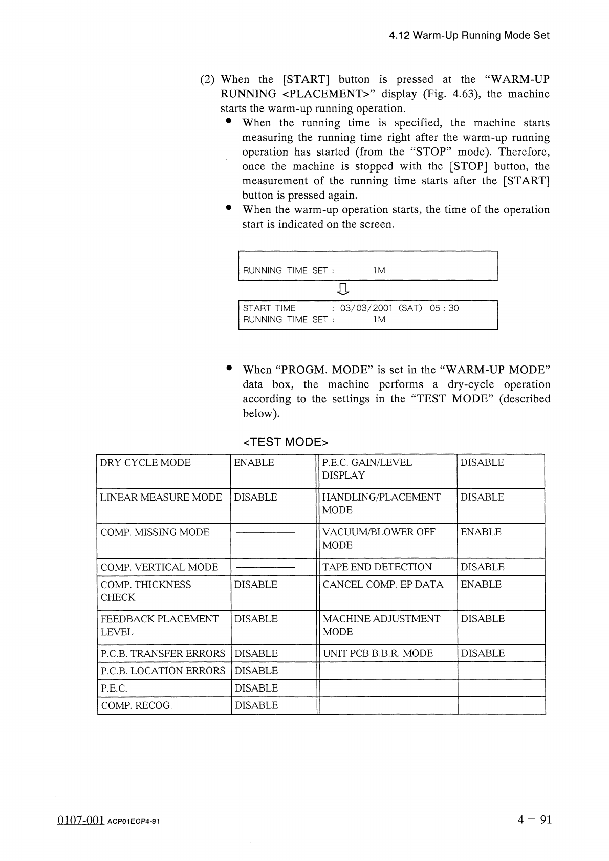
4.12 Warm - Up Running Mode Set ( 2 ) When the [ START ] button is pressed at the “ WARM - UP RUNNING 〈 PLACEMENT 〉 ” display ( Fig . 4.63 ) , the machine starts the warm - up running operation . • When the running time …

4.12
Warm
-
Up
Running
Mode
Set
Notes
:
Items
to
be
checked
before
operation
start
(
a
)
Warm
-
Up
Running
Operation
The
machine
does
not
perform
any
warm
-
up
running
operation
in
the
“
PLACE
”
or
the
“
PASS
”
mode
.
Confirm
that
“
PLACE
”
is
set
for
the
current
pattern
program
and
“
PLACE
.
MODE
”
is
indicated
above
the
[
PASS
/
PLACE
.
CHANGE
]
key
at
the
“
AUTO
OPN
.
SUB
-
MENU
”
display
.
The
vacuum
pump
is
automatically
turned
“
OFF
”
during
the
warm
-
up
running
operation
.
Be
sure
not
to
perform
the
warm
-
up
running
operation
with
a
component
being
picked
up
.
(
b
)
Remove
the
P
.
C
.
B
.
’
s
from
the
conveyor
and
the
X
/
Y
table
if
there
are
P
.
C
.
B
.
’
s
on
them
.
When
there
is
a
P
.
C
.
B
.
(
s
)
on
the
conveyor
and
/
or
the
X
/
Y
table
,
a
warning
message
is
issued
on
the
screen
.
(
c
)
When
another
message
is
issued
at
a
“
CHECK
”
display
,
check
the
contents
and
remove
the
cause
of
the
startup
error
.
•
After
specifying
each
parameter
,
press
the
[
WARM
-
UP
RUNNING
START
]
key
.
The
“
WARM
-
UP
RUNNING
〈
PLACEMENT
〉
,
,
display
(
Fig
.
4.63
)
appears
.
07
/
23
/
2001
(
MON
)
17
:
56
:
30
V
Z
3
2
1
6
C
6
I
STOP
I
I
WARM
-
UP
RUNNING
〈
PLACEMENT
〉
CURRENT
PRGM
:
COMMENT
«
1
U O O
-
P O O O O
(
O
)
F
O O
O
N O
.
:
F O O O
<
S
E
P
A
R A
T
E
D
>
S T E P
N O
.
F D R
.
氺 氺 氺氺 氺
ORIGIN
MONITOR
氺 氺 氺氷 氺
«
P
.
C
.
B
.
COUNTER
»
ROTARY
TURRET
RECOGNITION
P
.
C
.
B
.
TRANSFER
X
/
Y
TABLE
CAMERA
X
/
Y
FEEDER
AXIS
COMP
.
PICK
-
UP
(
Z
)
L
CNVR
.
WD
.
COMP
.
PLACE
.
(
Z
)
R
CNVR
.
WD
.
INPUT
MACHINE
OUTPUT
MACHINE
FURNACE
X
/
Y
CHUTE
WD
.
PROS
.
PROD
.
6
7
2
0
1
《
P
.
C
.
B
.
PRCS
.
TIME
))
10.05
SEC
.
HEAD
RUNNING
TIME
SET
:
1
M
Fig
.
4.63
0107
-
001
4
-
90
ACP
01
EOP
4
-
90
4.12
Warm
-
Up
Running
Mode
Set
(
2
)
When
the
[
START
]
button
is
pressed
at
the
“
WARM
-
UP
RUNNING
〈
PLACEMENT
〉
”
display
(
Fig
.
4.63
)
,
the
machine
starts
the
warm
-
up
running
operation
.
•
When
the
running
time
is
specified
,
the
machine
starts
measuring
the
running
time
right
after
the
warm
-
up
running
operation
has
started
(
from
the
“
STOP
”
mode
)
.
Therefore
,
the
machine
is
stopped
with
the
[
STOP
]
button
,
the
measurement
of
the
running
time
starts
after
the
[
START
]
button
is
pressed
again
.
•
When
the
warm
-
up
operation
starts
,
the
time
of
the
operation
start
is
indicated
on
the
screen
.
once
RUNNING
TIME
SET
:
1
M
:
03
/
03
/
2001
(
SAT
)
05
:
30
START
TIME
RUNNING
TIME
SET
:
1
M
•
When
“
PROGM
.
MODE
”
is
set
in
the
“
WARM
-
UP
MODE
”
data
box
,
the
machine
performs
a
dry
-
cycle
operation
according
to
the
settings
in
the
“
TEST
MODE
”
(
described
below
)
.
<
TEST
MODE
>
DRY
CYCLE
MODE
ENABLE
P
.
E
.
C
.
GAIN
/
LEVEL
DISPLAY
DISABLE
HANDLING
/
PLACEMENT
MODE
DISABLE
LINEAR
MEASURE
MODE
DISABLE
VACUUM
/
BLOWER
OFF
MODE
COMP
.
MISSING
MODE
ENABLE
COMP
.
VERTICAL
MODE
TAPE
END
DETECTION
DISABLE
CANCEL
COMP
.
EP
DATA
COMP
.
THICKNESS
CHECK
DISABLE
ENABLE
FEEDBACK
PLACEMENT
LEVEL
DISABLE
MACHINE
ADJUSTMENT
MODE
DISABLE
UNIT
PCB
B
.
B
.
R
.
MODE
DISABLE
P
.
C
.
B
.
TRANSFER
ERRORS
DISABLE
P
.
C
.
B
.
LOCATION
ERRORS
DISABLE
DISABLE
P
.
E
.
C
.
COMP
.
RECOG
.
DISABLE
4
-
91
0107
-
001
ACP
01
EOP
4
-
91
Page
5.1
Hierarchical
Structure
of
Manual
Mode
Displays
5.2
"
MANUAL
MODE
”
Display
5.3
Program
Change
5.4
Zeroing
Operation
5.5
Manual
Subsystem
Operation
5.6
Manual
Axis
Operation
5.7
Product
Change
5.7
.
1
Selection
of
Set
-
Up
Menus
and
Overall
Set
-
Up
Operation
5.7
.
2
Manual
Set
-
Up
Operation
of
L
/
R
Conveyor
and
X
/
Y
Table
Chute
Widths
5
-
n
fl
«
n
.
s
-
nm
ACP
01
EOPCC
5