1OPERATION_.pdf - 第39页
Unit : mm ( Front Side of Machine ) Notes : ( a ) A test may be required when there is a notch at the edges of the P . C . B . ( b ) Consider the tolerance of the hole position when LI is Min . 5 mm and leave some room i…
1.2
Specifications
Size
:
50
X
50
mm
-
330
X
250
mm
(
Four
Corners
:
R
1
^
R
1.5
mm
)
Thickness
:
0.5
-
2.5
mm
Warpage
:
0.2
mm
or
less
per
50
mm
(
Max
.
±
1
mm
)
Mass
:
Max
.
1.5
kg
(
mass
weighed
when
P
.
C
.
B
.
is
completed
)
Note
:
A
test
may
be
required
depending
upon
the
greater
warpage
,
the
material
or
the
shape
of
the
P
.
C
.
B
.
4
.
Applicable
P
.
C
.
B
.
Size
s
2.0
2.0
5
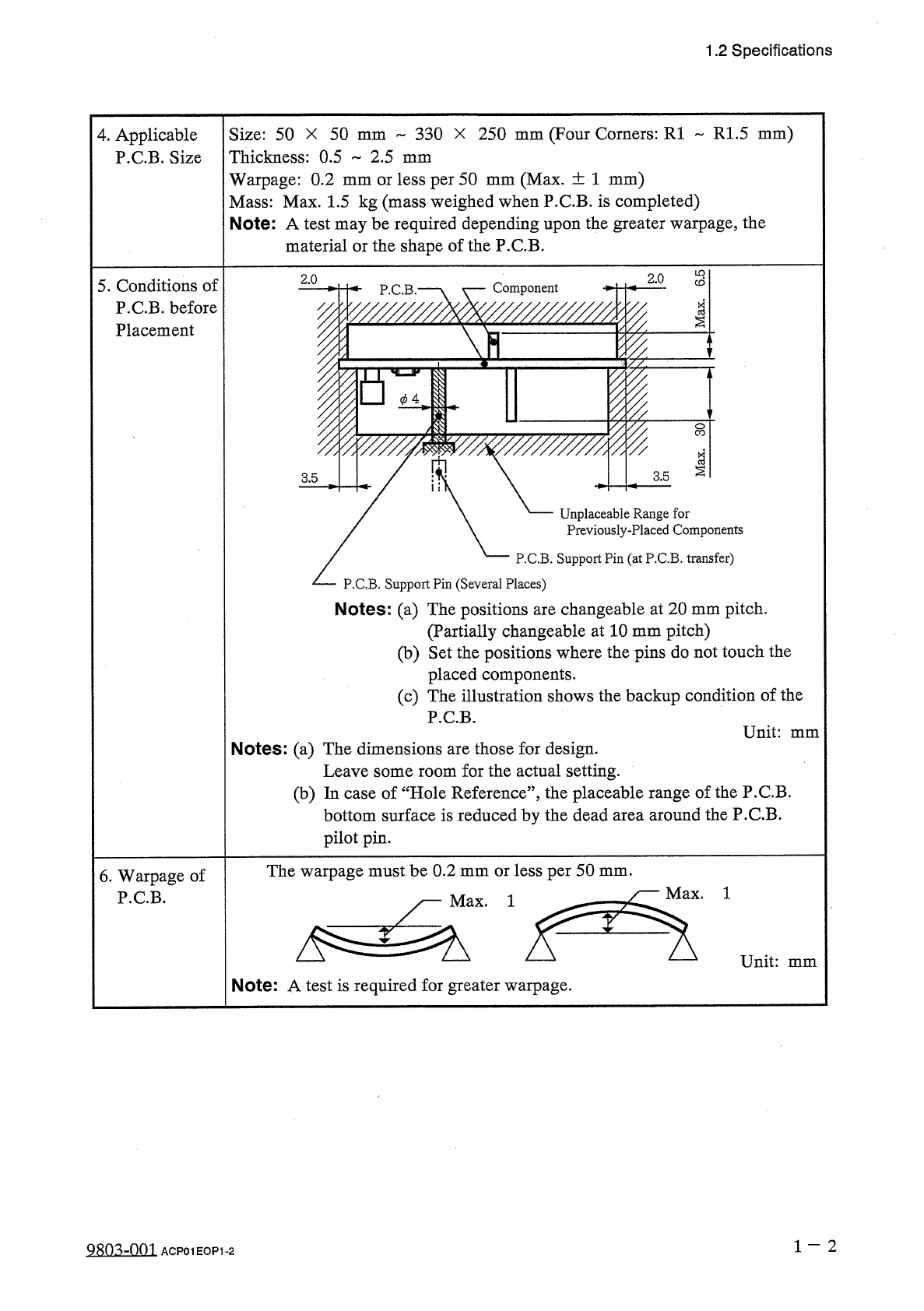
.
Conditions
of
P
.
C
.
B
.
before
Placement
Component
P
.
C
.
B
.
*
1
I
F
§
BZI
II
¥
3.5
3.5
Unplaceable
Range
for
Previously
-
Placed
Components
P
.
C
.
B
.
Support
Pin
(
at
P
.
C
.
B
.
transfer
)
P
.
C
.
B
.
Support
Pin
(
Several
Places
)
Notes
:
(
a
)
The
positions
are
changeable
at
20
mm
pitch
.
(
Partially
changeable
at
10
mm
pitch
)
(
b
)
Set
the
positions
where
the
pins
do
not
touch
the
placed
components
.
(
c
)
The
illustration
shows
the
backup
condition
of
the
P
.
C
.
B
.
Unit
:
mm
Notes
:
(
a
)
The
dimensions
are
those
for
design
.
Leave
some
room
for
the
actual
setting
.
(
b
)
In
case
of
“
Hole
Reference
”
,
the
placeable
range
of
the
P
.
C
.
B
.
bottom
surface
is
reduced
by
the
dead
area
around
the
P
.
C
.
B
.
pilot
pin
.
The
warpage
must
be
0.2
mm
or
less
per
50
mm
.
y
—
Max
.
1
6
.
Warpage
of
P
.
C
.
B
.
Note
:
A
test
is
required
for
greater
warpage
.
1
一
2
QRO
^
-
nm
ACP
01
HOP
1
-
2
Unit
:
mm
(
Front
Side
of
Machine
)
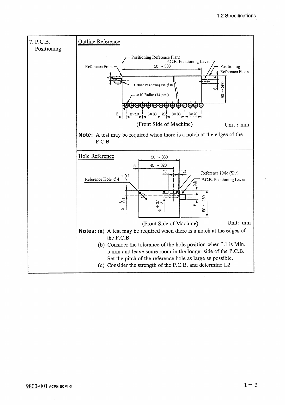
Notes
:
(
a
)
A
test
may
be
required
when
there
is
a
notch
at
the
edges
of
the
P
.
C
.
B
.
(
b
)
Consider
the
tolerance
of
the
hole
position
when
LI
is
Min
.
5
mm
and
leave
some
room
in
the
longer
side
of
the
P
.
C
.
B
.
Set
the
pitch
of
the
reference
hole
as
large
as
possible
.
(
c
)
Consider
the
strength
of
the
P
.
C
.
B
.
and
determine
L
2
.
1
-
3
98
Q
3
-
QQ
1
ACP
01
EOP
1
-
3
5
^
L
2
Reference
Hole
(
Slit
)
P
.
C
.
B
.
Positioning
Lever
,
+
0.1
Reference
Hole
cpA
0
Hole
Reference
50
330
40
~
320
LI
do
'
寸
1.2
Specifications
Outline
Reference
7
.
P
.
C
.
B
.
Positioning
Positioning
Reference
Plane
P
.
C
.
B
.
Positioning
Lever
50
330
Reference
Point
Positioning
Reference
Plane
LO
Outline
Positioning
Pin
<
t
>
10
CD
i
—
0
10
Roller
(
14
pcs
.
)
s
!
3
X
20
!
!
23
!
6
3
x
30
3
x
30
!
3
x
20
(
Front
Side
of
Machine
)
Note
:
A
test
may
be
required
when
there
is
a
notch
at
the
edges
of
the
P
.
C
.
B
.
Unit
:
mm
S
7
OLO
cot
1.2
Specifications
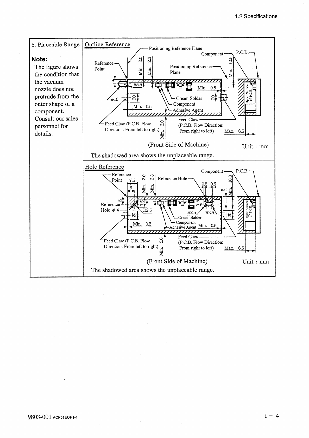
8
.
Placeable
Range
Outline
Reference
Positioning
Reference
Plane
Component
Note
:
The
figure
shows
the
condition
that
the
vacuum
nozzle
does
not
protrude
from
the
outer
shape
of
a
component
.
Consult
our
sales
personnel
for
details
.
CO
(
N
Reference
Point
Positioning
Reference
Plane
d
[
R
5.5
“
Min
.
0.5
:
-
Cream
Solder
Component
Adhesive
Agent
/
/
/
/
/
/
/
/
/
/
/
v
^
/
/
^
/
/
/
/
/
/
/
/
/
/
/
/
/
~
7
V
■
010
Min
.
0.5
Feed
Claw
(
P
.
C
.
B
.
Flow
Direction
:
From
right
to
left
)
Feed
Claw
(
P
.
C
.
B
.
Flow
§
Direction
:
From
left
to
right
)
^
Max
.
6.5
(
Front
Side
of
Machine
)
The
shadowed
area
shows
the
unplaceable
range
.
Unit
:
mm
Hole
Reference
P
.
C
.
B
Component
Reference
Point
7.5
CO
Reference
Hole
.
o
0.5
0.5
各
I
d
§
yz
Reference
Hole
<
/
>
4
'
-
7
•
tS
g
I
-
R
2.5
X
R
2.5
m
Solder
'
―
Component
■
Adhesive
Agent
Min
.
0.5
,
Feed
Claw
(
P
.
C
.
B
.
Flow
Direction
:
From
right
to
left
)
Max
.
6.5
Feed
Claw
(
P
.
C
.
B
.
Flow
S
Direction
:
From
left
to
right
)
(
Front
Side
of
Machine
)
The
shadowed
area
shows
the
unplaceable
range
.
Unit
:
mm
1
-
4
a
8
Q
3
zQQ
3
ACP
01
EOP
1
-
4