1OPERATION_.pdf - 第136页
2.16 Input and Selection of Program Data 2.16 Input and Selection of Program Data 2 , 16.1 Input of Program Data Data should be entered for pattern program data , component library data and operation mode to operate the …
2.15
Operation
Mode
of
Feeder
Carriages
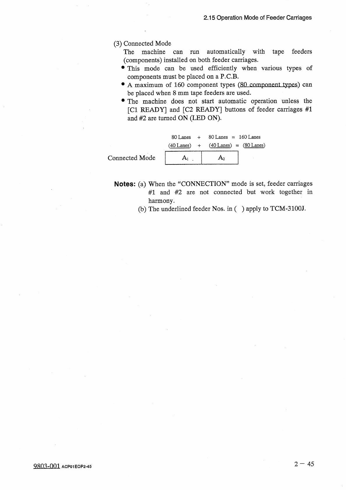
(
3
)
Connected
Mode
The
machine
automatically
with
tape
feeders
can
run
(
components
)
installed
on
both
feeder
carriages
.
•
This
mode
be
used
efficiently
when
components
must
be
placed
on
a
P
.
C
.
B
.
•
A
maximum
of
160
component
types
(
80
component
types
)
can
be
placed
when
8
mm
tape
feeders
are
used
.
•
The
machine
does
not
start
automatic
operation
unless
the
[
Cl
READY
]
and
[
C
2
READY
]
buttons
of
feeder
carriages
#
1
and
#
2
are
turned
ON
(
LED
ON
)
.
types
of
various
can
80
Lanes
+
80
Lanes
=
160
Lanes
(
40
Lanes
)
=
(
80
Lanes
)
(
40
Lanes
)
+
A
〗
Connected
Mode
Ai
.
Notes
:
(
a
)
When
the
“
CONNECTION
”
mode
is
set
,
feeder
carriages
not
connected
but
work
together
in
#
1
and
#
2
are
harmony
.
(
b
)
The
underlined
feeder
Nos
.
in
(
)
apply
to
TCM
-
3100
J
.
2
—
4 5
Q
朗
-
om
ACP
01
EOP
2
-
45
2.16
Input
and
Selection
of
Program
Data
2.16
Input
and
Selection
of
Program
Data
2
,
16.1
Input
of
Program
Data
Data
should
be
entered
for
pattern
program
data
,
component
library
data
and
operation
mode
to
operate
the
machine
automatically
.
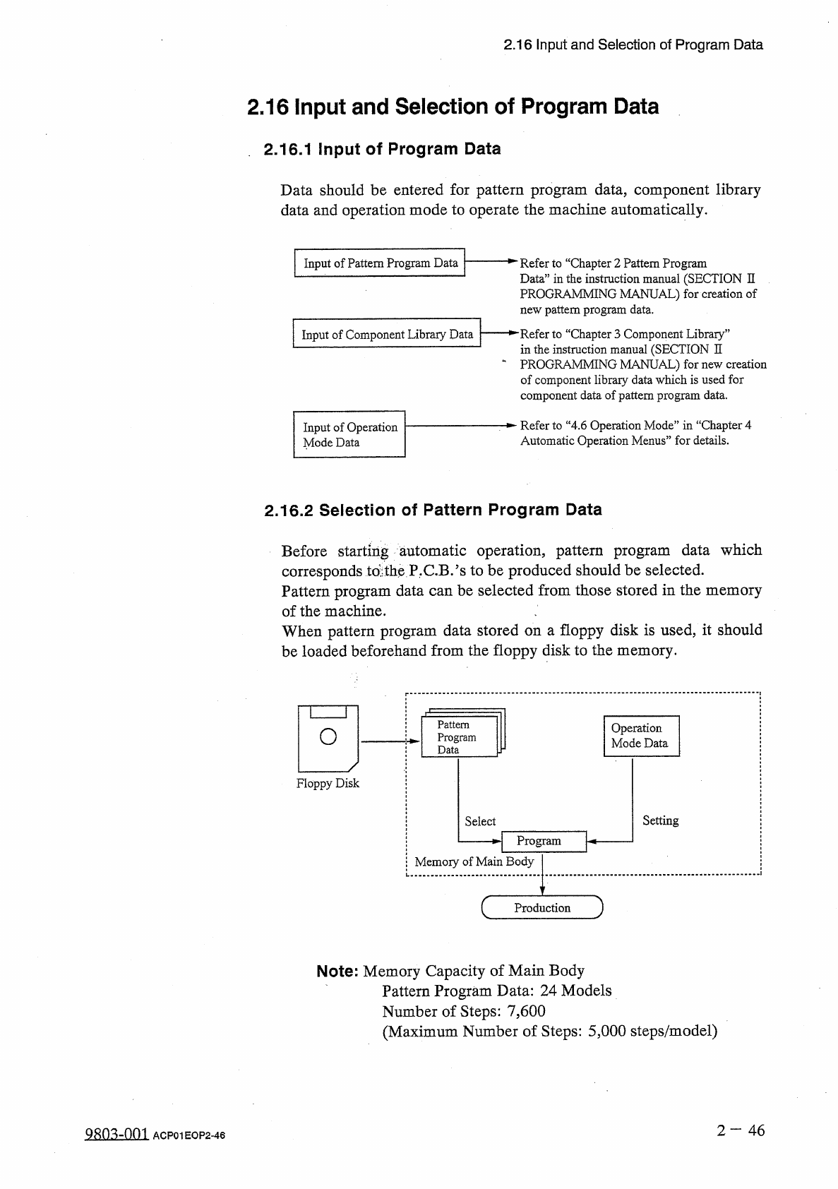
Input
of
Pattern
Program
Data
一
^
Refer
to
“
Chapter
2
Pattern
Program
Data
”
in
the
instruction
manual
(
SECTION
II
PROGRAMMING
MANUAL
)
for
creation
of
new
pattern
program
data
.
一
►
"
Refer
to
“
Chapter
3
Component
Library
”
in
the
instruction
manual
(
SECTION
II
一
PROGRAMMING
MANUAL
)
for
new
creation
of
component
libraiy
data
which
is
used
for
component
data
of
pattern
program
data
.
Input
of
Component
Library
Data
Refer
to
“
4.6
Operation
Mode
”
in
“
Chapter
4
Automatic
Operation
Menus
”
for
details
.
Input
of
Operation
Mode
Data
2.16
.
2
Selection
of
Pattern
Program
Data
Before
starting
automatic
operation
,
pattern
program
corresponds
td
tbe
P
.
C
.
B
/
s
to
be
produced
should
be
selected
.
Pattern
program
data
can
be
selected
from
those
stored
in
the
memory
of
the
machine
.
When
pattern
program
data
stored
on
a
floppy
disk
is
used
,
it
should
be
loaded
beforehand
from
the
floppy
disk
to
the
memory
.
data
which
Pattern
Program
Data
Operation
Mode
Data
O
Floppy
Disk
Setting
Select
H
Program
卜
Memory
of
Main
Body
Production
Note
:
Memory
Capacity
of
Main
Body
Pattern
Program
Data
:
24
Models
Number
of
Steps
:
7
,
600
(
Maximum
Number
of
Steps
:
5
,
000
steps
/
model
)
2
-
46
QRO
^
-
nm
ACP
01
EOP
2
-
46
Page
3
-
1
3.1
P
.
E
.
C
.
Recognition
Function
3.2
Equivalent
Repetitive
Pattern
Function
3.3
Differential
Repetitive
Pattern
Function
for
Mixed
Programs
3.4
Priority
Sorting
Function
3.5
Component
Shortage
Detection
Function
3.6
Automatic
Recovery
Function
3.7
Alternate
Mode
3.7
.
1
Alternate
Feeder
Axis
Data
3.7
.
2
Alternate
Feeder
Function
3.8
One
-
Touch
Jump
Function
(
Jump
to
Substitute
“
AUTO
OPN
.
MODE
<
PLACEMENT
>
>
,
Display
)
3.9
Device
Information
3.10
Simplified
Packaging
Direction
Change
Function
(
Editing
of
Component
Carriage
Data
)
3.11
Bad
Board
Reject
Function
3.12
Automatic
Offset
Teaching
Function
3.13
Warm
and
Cold
Start
Functions
3.14
HDD
/
FDD
Function
3.15
Maintenance
Warning
Function
3.16
Trash
Box
Fill
-
Up
Warning
Function
3.17
Data
Save
Function
(
Saving
the
displayed
data
on
floppy
disks
)
3
-
2
3
-
3
3
-
4
3
-
6
3
-
6
3
-
8
3
-
8
3
-
12
3
-
16
3
-
18
3
-
26
3
-
28
3
-
29
3
-
30
3
-
31
3
-
32
3
-
33
3
-
34
9902
-
002
ACP
01
EOPC
3