1OPERATION_.pdf - 第209页
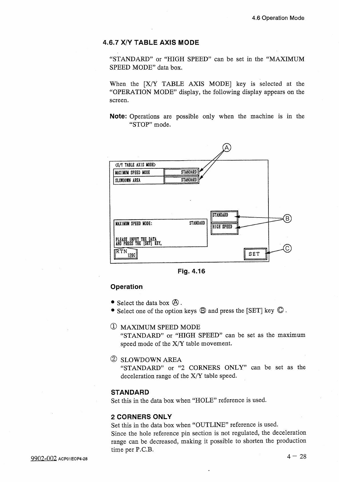
4.6 Operation Mode 4.6 . 7 X / Y TABLE AXIS MODE “ STANDARD ” or “ HIGH SPEED ” can be set in the “ MAXIMUM SPEED MODE ” data box . When the [ X / Y TABLE AXIS MODE ] key is selected at the “ OPERATION MODE ” display , t…
4.6
Operation
Mode
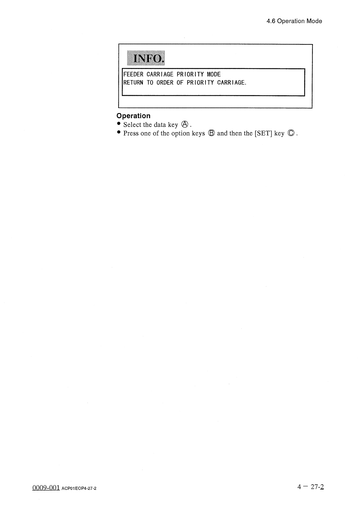
INFO
.
FEEDER
CARRIAGE
PRIORITY
MODE
RETURN
TO
ORDER
OF
PRIORITY
CARRIAGE
.
Operation
•
Select
the
data
key
@
.
•
Press
one
of
the
option
keys
®
and
then
the
[
SET
]
key
©
.
4
—
27
-
2
oooQ
-
nni
ACP
01
EOP
4
-
27
-
2
4.6
Operation
Mode
4.6
.
7
X
/
Y
TABLE
AXIS
MODE
“
STANDARD
”
or
“
HIGH
SPEED
”
can
be
set
in
the
“
MAXIMUM
SPEED
MODE
”
data
box
.
When
the
[
X
/
Y
TABLE
AXIS
MODE
]
key
is
selected
at
the
“
OPERATION
MODE
”
display
,
the
following
display
appears
on
the
screen
.
Note
:
Operations
“
STOP
”
mode
.
possible
only
when
the
machine
is
in
the
are
I
/
an
TABLE
AXIS
MODE
)
STANDARD
MAXIMUM
SPEED
MODE
STANDARD
SLOIDOIN
AREA
STANDARD
B
STANDARD
MAXIHUM
SPEED
MODE
:
HIGH
SPEED
DtCiCC
IHPIIT
Tnc
HiTi
H
沾
HIET
]
KEY
.
ffTN
12
Qc
|
SET
Fig
.
4.16
Operation
•
Select
the
data
box
@
.
•
Select
one
of
the
option
keys
®
and
press
the
[
SET
]
key
©
.
①
MAXIMUM
SPEED
MODE
“
STANDARD
:
speed
mode
of
the
X
/
Y
table
movement
.
HIGH
SPEED
”
can
be
set
as
the
maximum
or
②
SLOWDOWN
AREA
“
STANDARD
”
or
“
2
CORNERS
ONLY
”
can
be
set
as
the
deceleration
range
of
the
X
/
Y
table
speed
.
STANDARD
Set
this
in
the
data
box
when
“
HOLE
”
reference
is
used
.
2
CORNERS
ONLY
Set
this
in
the
data
box
when
“
OUTLINE
”
reference
is
used
.
Since
the
hole
reference
pin
section
is
not
regulated
,
the
deceleration
range
can
be
decreased
,
making
it
possible
to
shorten
the
production
time
per
P
.
C
.
B
.
4
—
2 8
9902
-
002
ACP
01
EOP
4
-
28
4.6
Operation
Mode
4.6
.
8
Setting
of
Trash
Box
Fill
-
Up
Warning
Mode
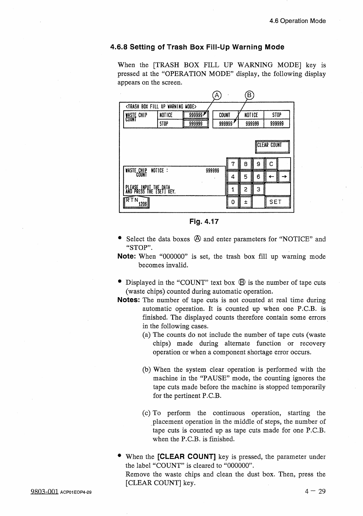
When
the
[
TRASH
BOX
FILL
UP
WARNING
MODE
]
key
is
pressed
at
the
“
OPERATION
MODE
”
display
,
the
following
display
appears
on
the
screen
.
@
g
)
〈
TRASH
BOX
FILL
UP
WARNING
MODE
〉
NOTICE
ft
999999
^
1
STOP
NOTICE
m
CHIP
COUNT
999999
|
999999
STOP
999999
999999
CLEAR
COUNT
9
C
7
8
m
\
m
WMV
NOTICE
:
999999
6
5
4
3
1
2
SET
0
±
Fig
.
4.17
•
Select
the
data
boxes
@
and
enter
'
parameters
for
“
NOTICE
”
and
“
STOP
”
.
Note
:
When
“
000000
”
is
set
,
the
trash
box
fill
up
warning
mode
becomes
invalid
.
•
Displayed
in
the
“
COUNT
”
text
box
®
is
the
number
of
tape
cuts
(
waste
chips
)
counted
during
automatic
operation
.
Notes
:
The
number
of
tape
cuts
is
not
counted
at
real
time
during
automatic
operation
.
It
is
counted
up
when
one
P
.
C
.
B
.
is
finished
.
The
displayed
counts
therefore
contain
some
errors
in
the
following
cases
.
(
a
)
The
counts
do
not
include
the
number
of
tape
cuts
(
waste
chips
)
made
during
alternate
function
or
recovery
operation
or
when
a
component
shortage
error
occurs
.
(
b
)
When
the
system
clear
operation
is
performed
with
the
machine
in
the
“
PAUSE
”
mode
,
the
counting
ignores
the
tape
cuts
made
before
the
machine
is
stopped
temporarily
for
the
pertinent
P
.
C
.
B
.
(
c
)
To
perform
the
continuous
operation
,
starting
the
placement
operation
in
the
middle
of
steps
,
the
number
of
tape
cuts
is
counted
up
as
tape
cuts
made
for
one
P
.
C
.
B
.
when
the
P
.
C
.
B
.
is
finished
.
•
When
the
[
CLEAR
COUNT
]
key
is
pressed
,
the
parameter
under
the
label
“
COUNT
”
is
cleared
to
“
000000
”
.
Remove
the
waste
chips
and
clean
the
dust
box
.
Then
,
press
the
[
CLEAR
COUNT
]
key
.
Q
80
^
-
001
4
一
29
ACP
01
EOP
4
-
29