1OPERATION_.pdf - 第247页
4.10 MANAGEMENT DATA • When one of the data keys is pressed , a feeder No . where the biggest parameter is set under the selected data key is displayed in the first line and feeder Nos . having the subsequent ( second , …
FDRVNI
COMPONENT
ID
L
NO
.
}
(
FEEDER
MESSAGE
RATE
(
XXXXX
DATA
)
)
T
DA
(
A
FDOESSBSE
HE
IE
SM
SCREENS
m
TOE
IAGE
/
TOTAL
COMPONENTS
)
RATE
■
NO
.
)
〈
FEEDER
MESSAGE
RATE
(
SAVED
DATA
}
)
NP
^
E
m
SA
/
^
RREHT
USE
SCREENS
TN
4135
FUIHO
SCREENS
WGE
p
^
h
N
靡義
嘱
|
=
)
〈
FEEDER
MESSAGE
RATE
(
CURRENT
DATA
)
〉
)
/
1
QQI
4.10
MANAGEMENT
DATA
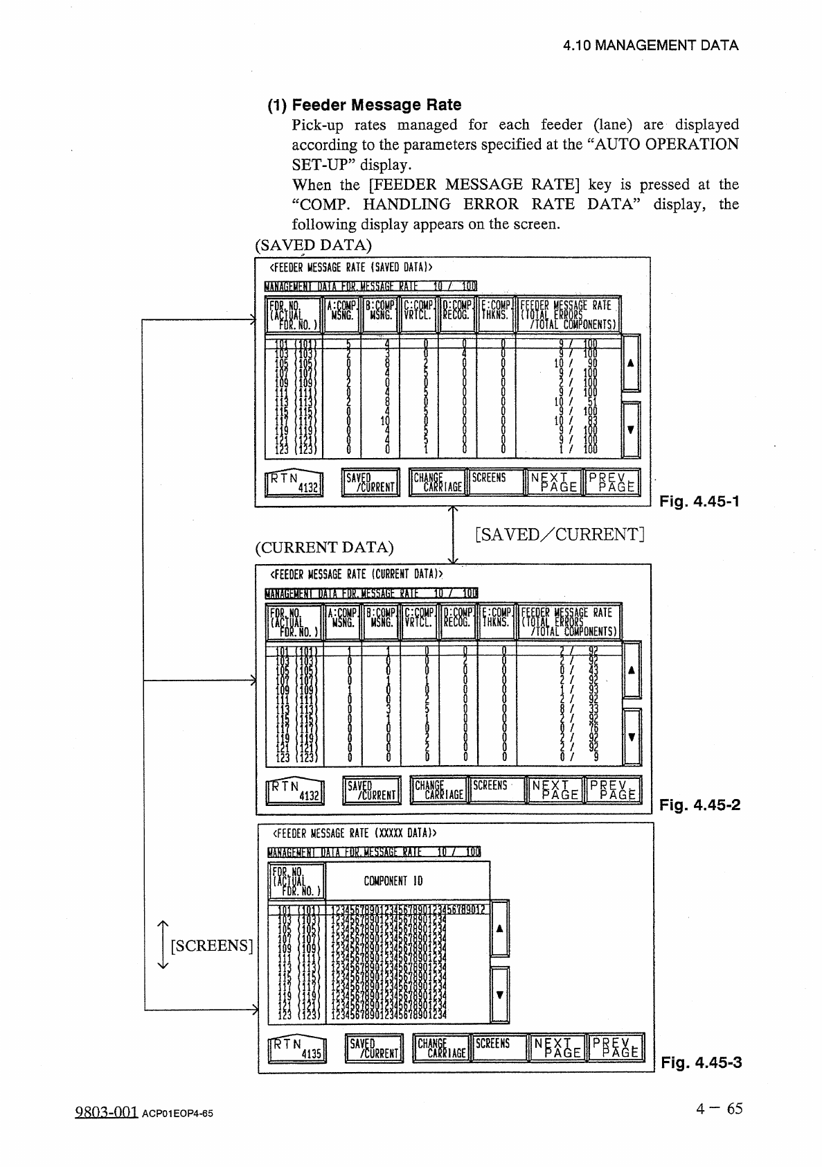
(
1
)
Feeder
Message
Rate
Pick
-
up
rates
managed
for
each
feeder
(
lane
)
according
to
the
parameters
specified
at
the
“
AUTO
OPERATION
SET
-
UP
”
display
.
When
the
[
FEEDER
MESSAGE
RATE
]
key
is
pressed
at
the
“
COMP
.
HANDLING
ERROR
RATE
DATA
”
display
,
the
following
display
appears
on
the
screen
.
(
SAVED
DATA
)
displayed
are
Fig
.
4.45
-
1
[
SAVED
/
CURRENT
]
(
CURRENT
DATA
)
Fig
.
4.45
-
2
[
SCREENS
]
Fig
.
4.45
-
3
4
一
65
QRo
^
-
nm
ACP
01
EOP
4
-
65
!
服州
3
!
此
1
圓
17
;
1
31
臛服
lif
州
■
财 喔
1
01
b
7
7
?
!
A
/
xvk
■
«
-
?
II
1
1
"
«
41
»
o
OQOOOlo
^
o
0900050
c
1
1
*
«
4 1
/
/
/
/
/
/
/
/
/
/
/
AUA
39
t
QX
/
-
909
s
AMMXU
1
-
111
■
■
■
■
_
■
■
邐
_
*
<
a
-
l
«
|
F
50
l
91357
Ayl
3
OOOI
-
-
-
-
«
-
l
r
.
?
»
?
-
I
-
l
■
■
-
l
«
*
J
-
IJ
■
!
牵
-
2328
-
-
93
nMW
7
»
/
/
/
/
/
/
/
/
/
.
H
02120020
A
/
*
1350
94
-
3579
*
-
3
o
nxuAuoi
?
?
111
Z
2
1
■
-
_
!
r
-
«
-
1
-
I
-
-
rDTAM
-
i
OJCJ
7913
•
■
1
•
■
!
?
屬
!
<
■
易
i
■
-
»
屬
i
.
4
■
4.10
MANAGEMENT
DATA
•
When
one
of
the
data
keys
is
pressed
,
a
feeder
No
.
where
the
biggest
parameter
is
set
under
the
selected
data
key
is
displayed
in
the
first
line
and
feeder
Nos
.
having
the
subsequent
(
second
,
third
,
fourth
,
.
..
)
biggest
parameters
follow
.
When
the
[
FDR
.
NO
.
(
ACTUAL
FDR
.
NO
.
)
]
key
is
pressed
,
feeder
Nos
.
are
arranged
in
their
initial
order
.
•
When
the
[
CHANGE
CARRIAGE
]
key
is
pressed
,
the
display
for
the
other
feeder
carriage
appears
on
the
screen
.
•
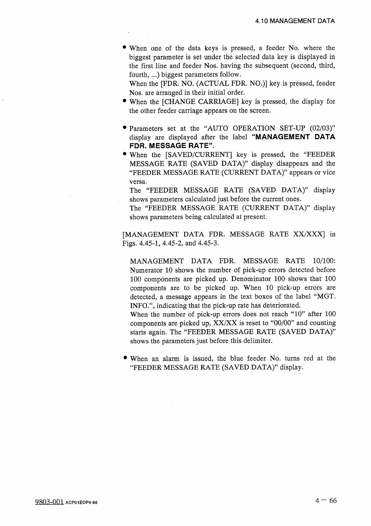
Parameters
set
at
the
“
AUTO
OPERATION
SET
-
UP
(
02
/
03
)
”
displayed
after
the
label
“
MANAGEMENT
DATA
display
FDR
.
MESSAGE
RATE
"
.
are
•
When
the
[
SAVED
/
CURRENT
]
key
is
pressed
,
the
“
FEEDER
MESSAGE
RATE
(
SAVED
DATA
)
”
display
disappears
and
the
“
FEEDER
MESSAGE
RATE
(
CURRENT
DATA
)
”
appears
or
vice
versa
.
The
“
FEEDER
MESSAGE
RATE
(
SAVED
DATA
)
,
,
display
shows
parameters
calculated
just
before
the
current
ones
.
The
“
FEEDER
MESSAGE
RATE
(
CURRENT
DATA
)
,,
display
shows
parameters
being
calculated
at
present
.
[
MANAGEMENT
DATA
FDR
.
MESSAGE
RATE
XX
/
XXX
]
in
Figs
.
4.45
-
1
,
4.45
-
2
,
and
4.45
-
3
.
MANAGEMENT
DATA
FDR
.
MESSAGE
RATE
10
/
100
:
Numerator
10
shows
the
number
of
pick
-
up
errors
detected
before
100
components
are
picked
up
.
Denominator
100
shows
that
100
components
are
to
be
picked
up
.
When
10
pick
-
up
detected
,
a
message
appears
in
the
text
boxes
of
the
label
“
MGT
.
INFO
.
”
,
indicating
that
the
pick
-
up
rate
has
deteriorated
.
When
the
number
of
pick
-
up
errors
does
not
reach
“
10
”
after
100
components
are
picked
up
,
XX
/
XX
is
reset
to
“
00
/
00
”
and
counting
starts
again
.
The
“
FEEDER
MESSAGE
RATE
(
SAVED
DATA
)
,,
shows
the
parameters
just
before
this
delimiter
.
errors
are
•
When
an
alarm
is
issued
,
the
blue
feeder
No
.
turns
red
at
the
“
FEEDER
MESSAGE
RATE
(
SAVED
DATA
)
,
,
display
.
4
—
66
明
m
-
001
ACP
01
EOP
4
-
66
〈
NOZZLE
MESSAGE
RATE
(
CURRENT
DATA
)
〉
BfflSEBEHEIBn
HDZ
3
ESSSE
15
IE
b
/
bOI
:
COMP
.
HEAD
A
:
HKNS
.
•
NOZZLE
M
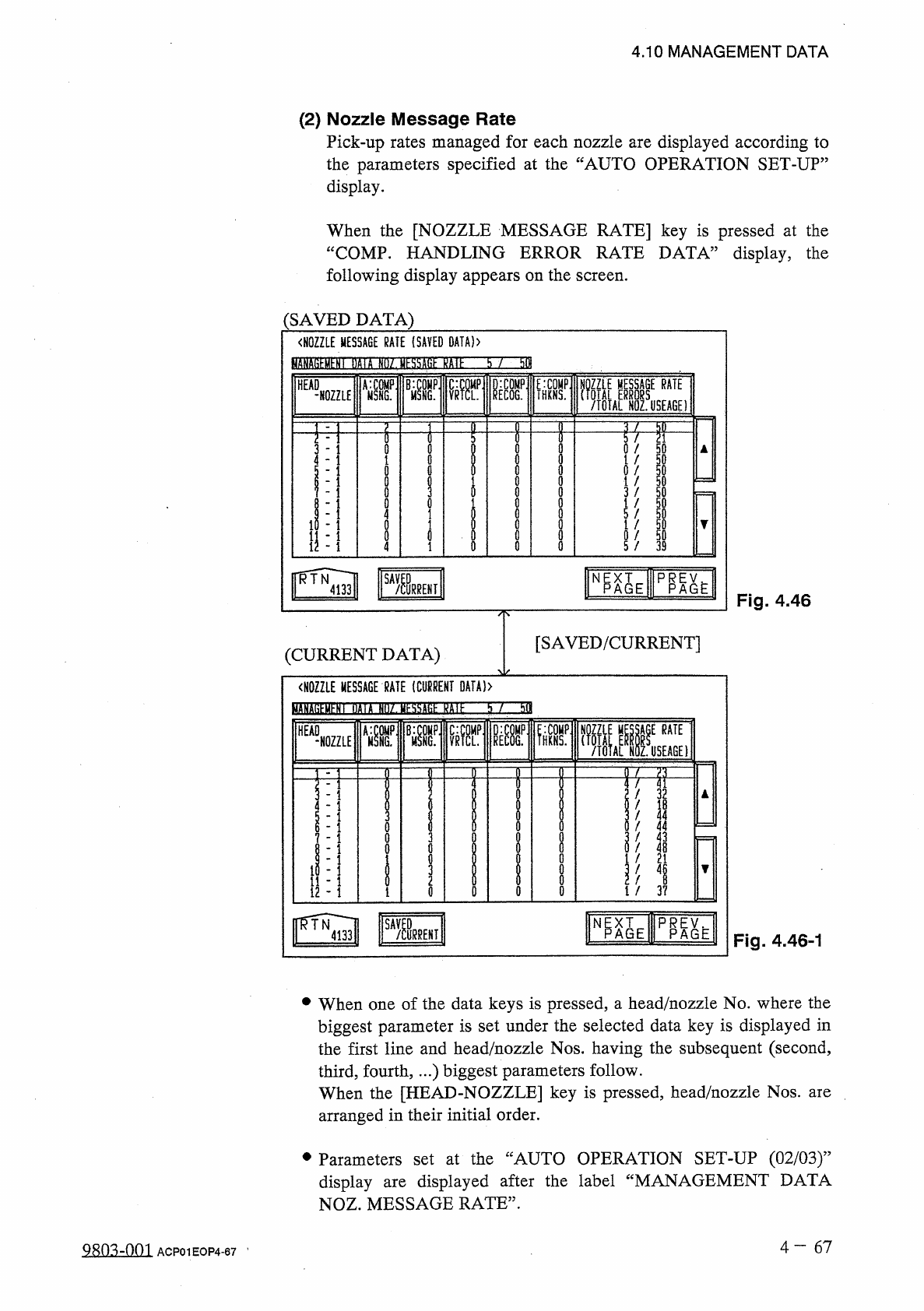
Fig
.
4.46
-
1
N p X T
—
P
^
AGE
A G E
Fig
.
4.46
[
SAVED
/
CURRENT
]
(
CURRENT
DATA
)
•
When
one
of
the
data
keys
is
pressed
,
a
head
/
nozzle
No
.
where
the
biggest
parameter
is
set
under
the
selected
data
key
is
displayed
in
the
first
line
and
head
/
nozzle
Nos
.
having
the
subsequent
(
second
,
third
,
fourth
,
…
)
biggest
parameters
follow
.
When
the
[
HEAD
-
NOZZLE
]
key
is
pressed
,
head
/
nozzle
Nos
.
arranged
in
their
initial
order
.
are
•
Parameters
set
at
the
“
AUTO
OPERATION
SET
-
UP
(
02
/
03
)
,
,
display
are
displayed
NOZ
.
MESSAGE
RATE
”
.
after
the
label
“
MANAGEMENT
DATA
4
—
6 7
mimi
ACP
01
EOP
4
-
67
4
,
10
MANAGEMENT
DATA
(
2
)
Nozzle
Message
Rate
Pick
-
up
rates
managed
for
each
nozzle
are
displayed
according
to
the
parameters
specified
at
the
“
AUTO
OPERATION
SET
-
UP
”
display
.
When
the
[
NOZZLE
MESSAGE
RATE
]
key
is
pressed
at
the
“
COMP
.
HANDLING
ERROR
RATE
DATA
”
display
,
the
following
display
appears
on
the
screen
.
(
SAVED
DATA
)
〈
NOZZLE
MESSAGE
RATE
(
SAVED
DATA
)
〉
fciATO
^
HY
'
nflift
SSZJEISEIinEZZn
38
-
-
NOZZLE
W
'
V
遛
H
勰
p
_
f
/
TOTAL
NOZ
.
USEAGE
)
RATE
HEAD
RATE
/
3 2
/
I B
/
4 4
!
4 4
/
4 3
/
4
B
f
2 1
I
/
i
/
3 7
VG
0
l
«
-
J
-
«
■
■
■
■
■
i
i
静
i
.
i
t
>
t
,
?
ooco
2
ili
2
u
woonu
-
UQ
9
-
555553
^
/
/
/
/
/
/
/
/
/
.
/
2
bolol
3
l
5
to
5
«
-
-
J
1
«
tJlJ
IJ
-
1
»
»
r
-
-
«
.
隹
舞
l
t
i
i
i
i
i