1OPERATION_.pdf - 第63页
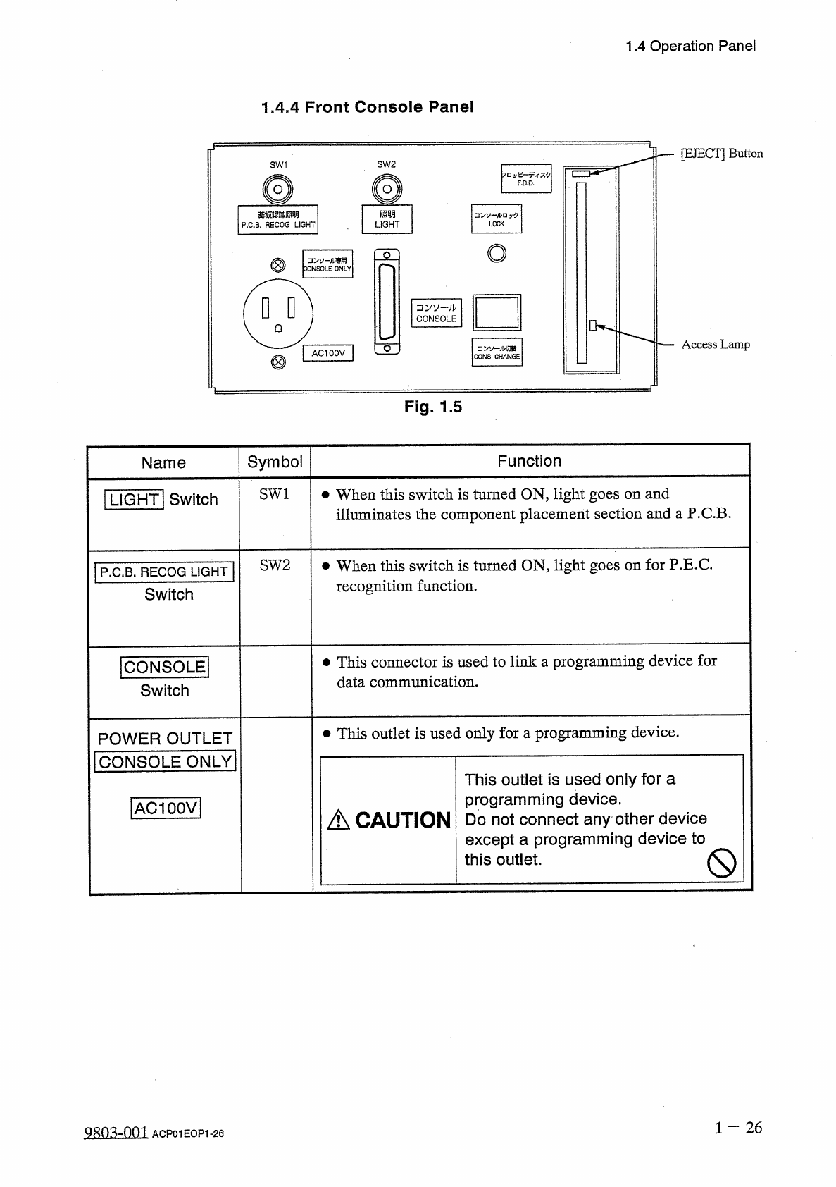
1.4 Operation Panel 1.4 . 4 Front Console Panel [ EJECT ] Button SW 1 SW 2 F . D . D . 照明 基板認雜照明 P . C . B . RECOG LIGHT LOCK LIGHT o o . 儿専用 CONSOLE ONLY □ VV - ; b CONSOLE Access Lamp o CONS CHANGE AC 100 V Fig . 1.5 S…
1.4
Operation
Panel
Switch
Name
Symbol
Function
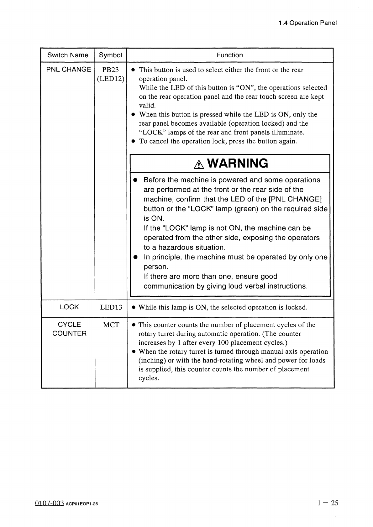
PNLCHANGE
•
This
button
is
used
to
select
either
the
front
or
the
rear
operation
panel
.
While
the
LED
of
this
button
is
‘
‘
ON
’’
,
the
operations
selected
on
the
rear
operation
panel
and
the
rear
touch
screen
are
kept
valid
.
•
When
this
button
is
pressed
while
the
LED
is
ON
,
only
the
rear
panel
becomes
available
(
operation
locked
)
and
the
“
LOCK
”
lamps
of
the
rear
and
front
panels
illuminate
.
•
To
cancel
the
operation
lock
,
press
the
button
again
.
PB
23
(
LED
12
)
A
WARNING
•
Before
the
machine
is
powered
and
some
operations
are
performed
at
the
front
or
the
rear
side
of
the
machine
,
confirm
that
the
LED
of
the
[
PNL
CHANGE
]
button
or
the
“
LOCK
”
lamp
(
green
)
on
the
required
side
is
ON
.
If
the
“
LOCK
”
lamp
is
not
ON
,
the
machine
can
be
operated
from
the
other
side
,
exposing
the
operators
to
a
hazardous
situation
.
•
In
principle
,
the
machine
must
be
operated
by
only
one
person
.
If
there
are
more
than
one
,
ensure
good
communication
by
giving
loud
verbal
instructions
.
LOCK
•
While
this
lamp
is
ON
,
the
selected
operation
is
locked
.
LED
13
CYCLE
COUNTER
•
This
counter
counts
the
number
of
placement
cycles
of
the
rotary
turret
during
automatic
operation
.
(
The
counter
increases
by
1
after
every
100
placement
cycles
.
)
•
When
the
rotary
turret
is
turned
through
manual
axis
operation
(
inching
)
or
with
the
hand
-
rotating
wheel
and
power
for
loads
is
supplied
,
this
counter
counts
the
number
of
placement
cycles
.
MCT
1
-
25
0107
-
003
ACP
01
EOP
1
-
25
1.4
Operation
Panel
1.4
.
4
Front
Console
Panel
[
EJECT
]
Button
SW
1
SW
2
F
.
D
.
D
.
照明
基板認雜照明
P
.
C
.
B
.
RECOG
LIGHT
LOCK
LIGHT
o
o
.
儿専用
CONSOLE
ONLY
□
VV
-
;
b
CONSOLE
Access
Lamp
o
CONS
CHANGE
AC
100
V
Fig
.
1.5
Symbol
Function
Name
SW
1
•
When
this
switch
is
turned
ON
,
light
goes
on
and
illuminates
the
component
placement
section
and
a
P
.
C
.
B
.
I
LIGHT
!
Switch
SW
2
•
When
this
switch
is
turned
ON
,
light
goes
on
for
P
.
E
.
C
.
recognition
function
.
P
.
C
.
B
.
RECOG
LIGHT
Switch
•
This
connector
is
used
to
link
a
programming
device
for
data
communication
.
ICONSOLEI
Switch
•
This
outlet
is
used
only
for
a
programming
device
.
POWER
OUTLET
I
CONSOLE
ONLY
|
This
outlet
is
used
only
for
a
programming
device
.
Do
not
connect
any
other
device
except
a
programming
device
to
this
outlet
.
[
ACIOOVl
A
CAUTION
Q
1
-
26
QRO
^
-
nm
ACP
01
EOP
1
-
26
1.4
Operation
Panel
Symbol
Function
Name
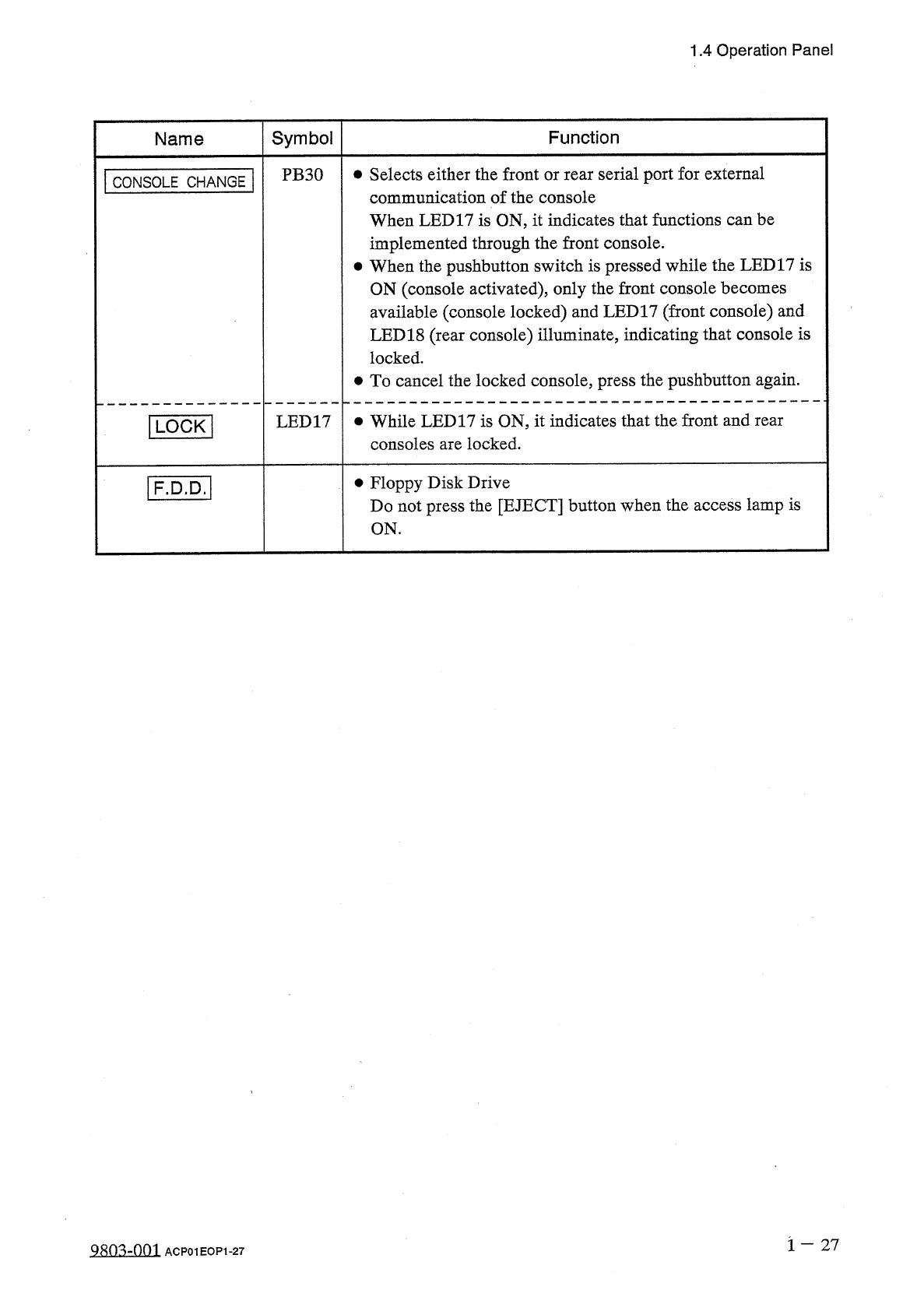
PB
30
•
Selects
either
the
front
or
rear
serial
port
for
external
communication
of
the
console
When
LED
17
is
ON
,
it
indicates
that
functions
can
be
implemented
through
the
front
console
.
•
When
the
pushbutton
switch
is
pressed
while
the
LED
17
is
ON
(
console
activated
)
,
only
the
front
console
becomes
available
(
console
locked
)
and
LED
17
(
front
console
)
and
LED
18
(
rear
console
)
illuminate
,
indicating
that
console
is
locked
.
•
To
cancel
the
locked
console
,
press
the
pushbutton
again
.
CONSOLE
CHANGE
LED
17
•
While
LED
17
is
ON
,
it
indicates
that
the
front
and
rear
consoles
are
locked
.
[
LOCK
]
•
Floppy
Disk
Drive
Do
not
press
the
[
EJECT
]
button
when
the
access
lamp
is
ON
.
[
F
.
D
.
D
.
1
1
-
27
9
^
0
^
-
001
ACP
01
EOP
1
-
27