1OPERATION_.pdf - 第37页
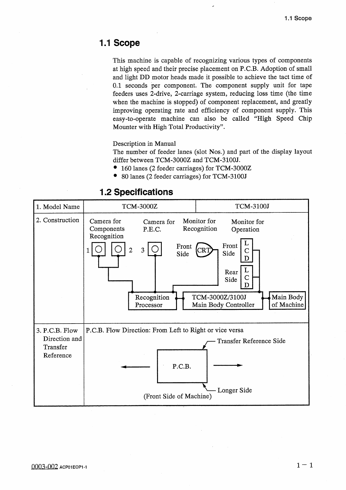
2 . Construction Camera for Monitor for P . E . C . Camera for Components Recognition Monitor for Recognition Operation Front Side Front Side 1 O O 2 3 O Rear Side Recognition Processor Main Body of Machine TCM - 3000 Z …
娜 灌
1
…
.
Page
1.1
Scope
1.2
Specifications
1.3
Structure
and
Names
1.4
Operation
Panel
1.4
.
1
Power
Breaker
Crank
1.4
.
2
Front
Operation
Panel
1.4
.
3
Rear
Operation
Panel
1.4
.
4
Front
Console
Panel
1.4
.
5
Rear
Console
Panel
1.4
.
6
[
C
1
READY
]
and
[
C
2
READY
]
Buttons
1.5
Scope
of
Actions
1.5
.
1
P
.
C
.
B
.
Transfer
1.5
.
2
Component
Placement
Section
1.6
Construction
of
Feeder
Carriages
•
•
•
1.7
Installation
of
Tape
Feeders
on
Feeder
Carriages
1.8
Placement
Head
Section
1.9
List
of
Nozzle
Types
1.10
[
PNL
CHANGE
]
Buttons
1.11
[
OPERATION
]
Switch
1.12
Recognition
Monitor
1
1
-
17
1
-
18
1
-
18
1
-
20
1
-
23
1
-
26
1
-
28
1
-
30
1
-
31
1
-
31
1
-
32
1
-
35
1
-
36
1
-
39
1
-
41
1
-
44
1
-
46
1
-
47
9803
-
001
ACP
01
EOPCC
1
2
.
Construction
Camera
for
Monitor
for
P
.
E
.
C
.
Camera
for
Components
Recognition
Monitor
for
Recognition
Operation
Front
Side
Front
Side
1
O
O
2
3
O
Rear
Side
Recognition
Processor
Main
Body
of
Machine
TCM
-
3000
Z
/
3100
J
Main
Body
Controller
3
.
P
.
C
.
B
.
Flow
P
.
C
.
B
.
Flow
Direction
:
From
Left
to
Right
or
vice
versa
Direction
and
Transfer
Reference
Transfer
Reference
Side
P
.
C
.
B
.
Longer
Side
(
Front
Side
of
Machine
)
1
一
1
0003
-
002
ACPOIEOPM
1.1
Scope
1.1
Scope
This
machine
is
capable
of
recognizing
various
types
of
components
at
high
speed
and
their
precise
placement
on
P
.
C
.
B
.
Adoption
of
small
and
light
DD
motor
heads
made
it
possible
to
achieve
the
tact
time
of
0.1
seconds
per
component
.
The
component
supply
unit
for
tape
feeders
uses
2
-
drive
,
2
-
carriage
system
,
reducing
loss
time
(
the
time
when
the
machine
is
stopped
)
of
component
replacement
,
and
greatly
improving
operating
rate
and
efficiency
of
component
supply
.
This
easy
-
to
-
operate
machine
Mounter
with
High
Total
Productivity
55
.
also
be
called
“
High
Speed
Chip
can
Description
in
Manual
The
number
of
feeder
lanes
(
slot
Nos
.
)
and
part
of
the
display
layout
differ
between
TCM
-
3000
Z
and
TCM
-
3100
J
.
•
160
lanes
(
2
feeder
carriages
)
for
TCM
-
3000
Z
•
80
lanes
(
2
feeder
carriages
)
for
TCM
-
3100
J
1.2
Specifications
TCM
-
3100
J
TCM
-
3000
Z
1
.
Model
Name
L
c
D
L
c
D
1.2
Specifications
Size
:
50
X
50
mm
-
330
X
250
mm
(
Four
Corners
:
R
1
^
R
1.5
mm
)
Thickness
:
0.5
-
2.5
mm
Warpage
:
0.2
mm
or
less
per
50
mm
(
Max
.
±
1
mm
)
Mass
:
Max
.
1.5
kg
(
mass
weighed
when
P
.
C
.
B
.
is
completed
)
Note
:
A
test
may
be
required
depending
upon
the
greater
warpage
,
the
material
or
the
shape
of
the
P
.
C
.
B
.
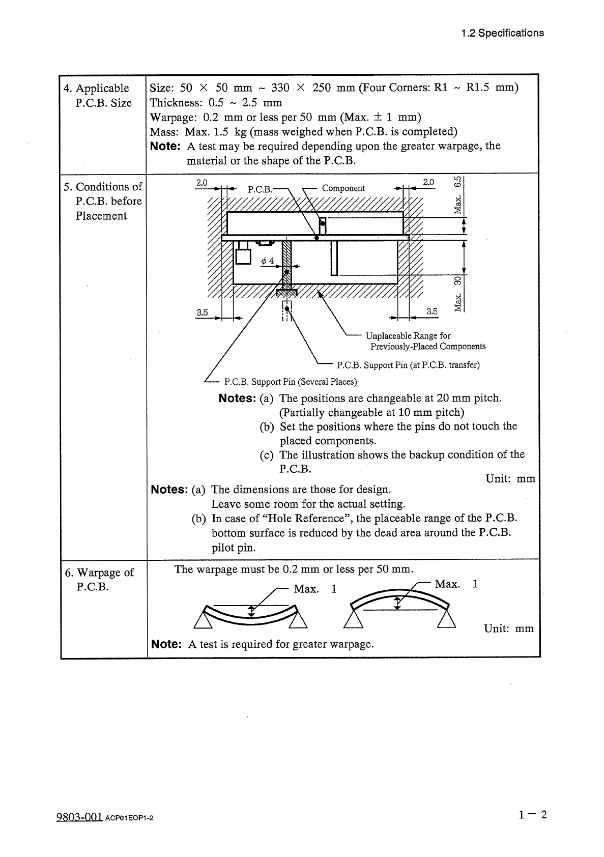
4
.
Applicable
P
.
C
.
B
.
Size
s
2.0
2.0
5
.
Conditions
of
P
.
C
.
B
.
before
Placement
Component
P
.
C
.
B
.
*
1
I
F
§
BZI
II
¥
3.5
3.5
Unplaceable
Range
for
Previously
-
Placed
Components
P
.
C
.
B
.
Support
Pin
(
at
P
.
C
.
B
.
transfer
)
P
.
C
.
B
.
Support
Pin
(
Several
Places
)
Notes
:
(
a
)
The
positions
are
changeable
at
20
mm
pitch
.
(
Partially
changeable
at
10
mm
pitch
)
(
b
)
Set
the
positions
where
the
pins
do
not
touch
the
placed
components
.
(
c
)
The
illustration
shows
the
backup
condition
of
the
P
.
C
.
B
.
Unit
:
mm
Notes
:
(
a
)
The
dimensions
are
those
for
design
.
Leave
some
room
for
the
actual
setting
.
(
b
)
In
case
of
“
Hole
Reference
”
,
the
placeable
range
of
the
P
.
C
.
B
.
bottom
surface
is
reduced
by
the
dead
area
around
the
P
.
C
.
B
.
pilot
pin
.
The
warpage
must
be
0.2
mm
or
less
per
50
mm
.
y
—
Max
.
1
6
.
Warpage
of
P
.
C
.
B
.
Note
:
A
test
is
required
for
greater
warpage
.
1
一
2
QRO
^
-
nm
ACP
01
HOP
1
-
2