1OPERATION_.pdf - 第30页
Safety Switches Safety Switches • When an error is detected in the machine , the safety features are designed to stop the dangerous moving mechanisms of the machine . Everything is processed on the machine without using …
Warning
Labels
(
Location
and
Description
)
No
.
Warning
Labels
Description
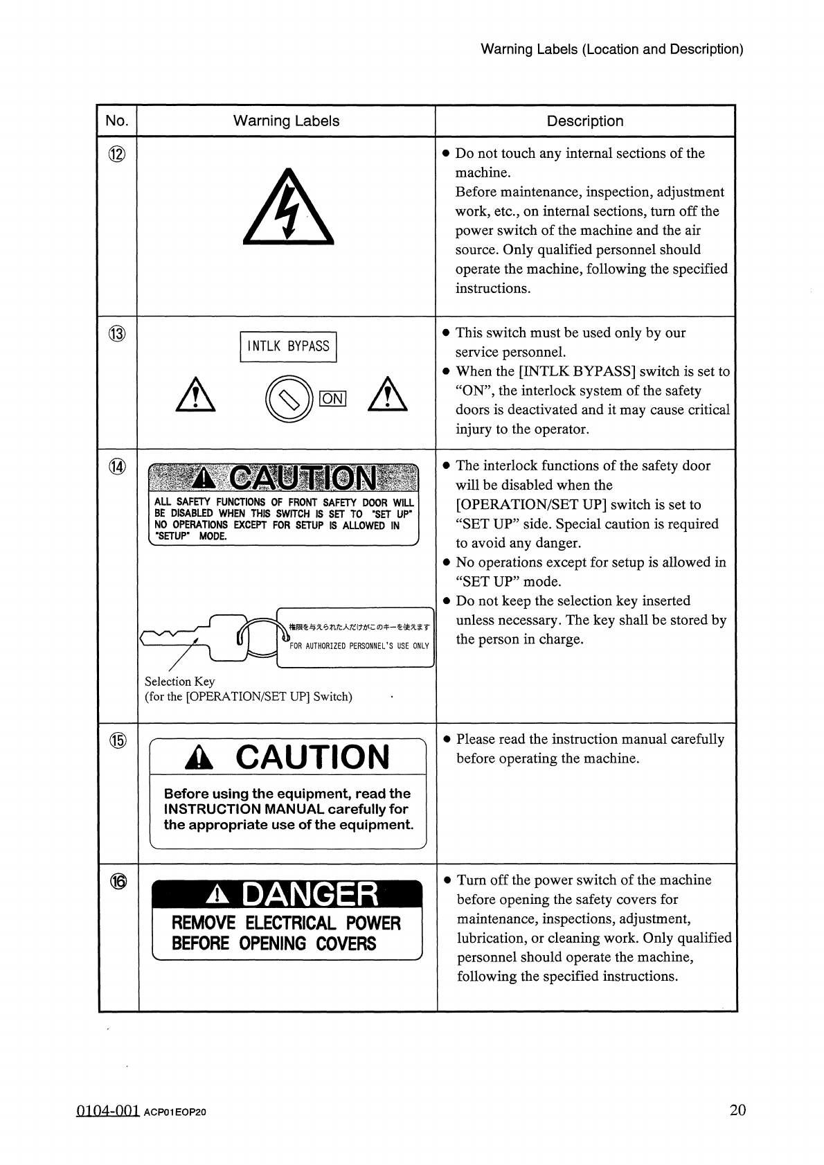
⑫
•
Do
not
touch
any
internal
sections
of
the
machine
.
Before
maintenance
,
inspection
,
adjustment
work
,
etc
.
,
on
internal
sections
,
turn
off
the
power
switch
of
the
machine
and
the
air
source
.
Only
qualified
personnel
should
operate
the
machine
,
following
the
specified
instructions
.
A
\
⑬
•
This
switch
must
be
used
only
by
our
service
personnel
.
•
When
the
[
INTLK
BYPASS
]
switch
is
set
to
“
ON
”
,
the
interlock
system
of
the
safety
doors
is
deactivated
and
it
may
cause
critical
injury
to
the
operator
.
INTLK
BYPASS
A
(
©
■
A
⑭
•
The
interlock
functions
of
the
safety
door
will
be
disabled
when
the
[
OPERATION
/
SET
UP
]
switch
is
set
to
“
SET
UP
”
side
.
Special
caution
is
required
to
avoid
any
danger
.
•
No
operations
except
for
setup
is
allowed
in
“
SETUP
”
mode
.
•
Do
not
keep
the
selection
key
inserted
unless
necessary
.
The
key
shall
be
stored
by
the
person
in
charge
.
NO
(
"
SET
権限奄与无
tifc
人圮
i
力
!
牛一奄使无袤
r
FOR
AUTHORIZED
PERSONNEL
’
S
USE
ONLY
Selection
Key
(
for
the
[
OPERATION
/
SET
UP
]
Switch
)
⑮
•
Please
read
the
instruction
manual
carefully
before
operating
the
machine
.
A
CAUTION
Before
using
the
equipment
,
read
the
INSTRUCTION
MANUAL
carefully
for
the
appropriate
use
of
the
equipment
.
⑯
Turn
off
the
power
switch
of
the
machine
before
opening
the
safety
covers
for
maintenance
,
inspections
,
adjustment
,
lubrication
,
or
cleaning
work
.
Only
qualified
personnel
should
operate
the
machine
,
following
the
specified
instructions
.
A
DANGER
REMOVE
ELECTRICAL
POWER
BEFORE
OPENING
COVERS
0104
-
001
ACP
01
EOP
20
20
Safety
Switches
Safety
Switches
•
When
an
error
is
detected
in
the
machine
,
the
safety
features
are
designed
to
stop
the
dangerous
moving
mechanisms
of
the
machine
.
Everything
is
processed
on
the
machine
without
using
any
software
application
on
the
computer
side
.
•
The
figures
below
show
TCM
-
3000
Z
.
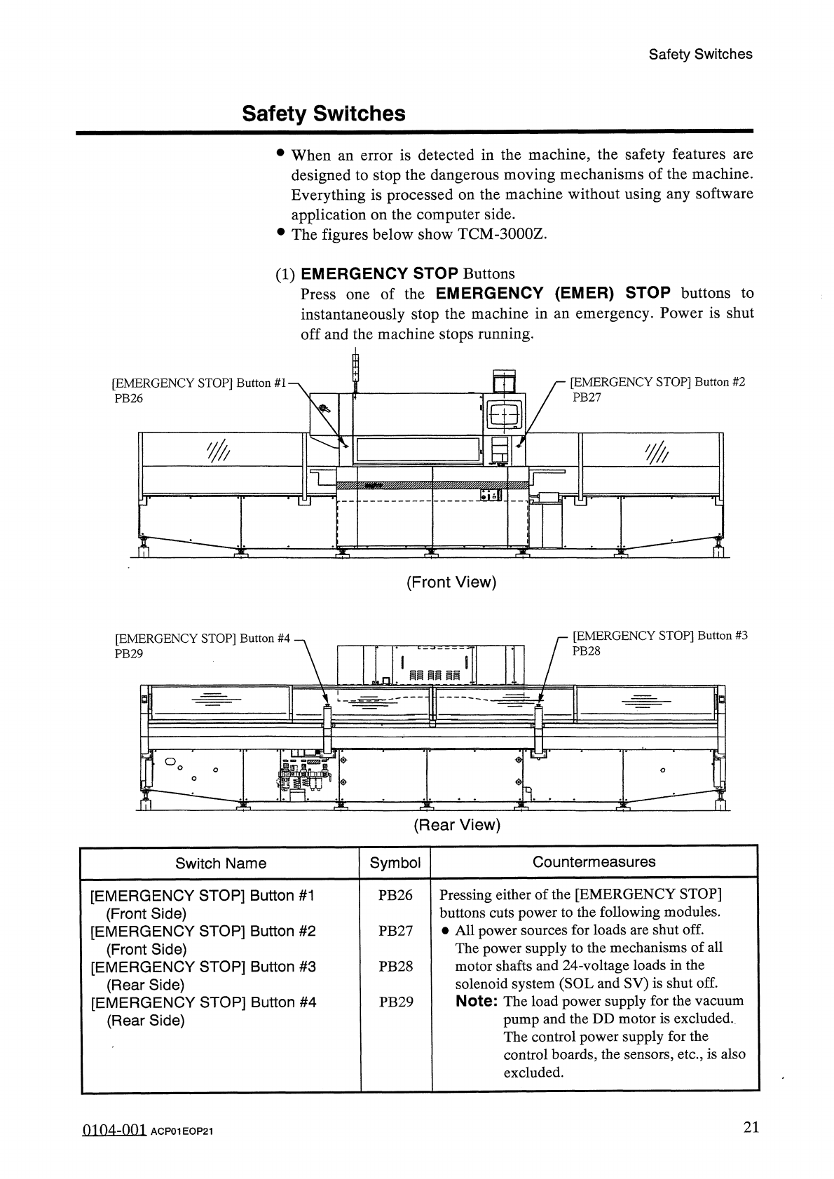
(
1
)
EMERGENCY
STOP
Buttons
Press
one
of
the
EMERGENCY
(
EMER
)
STOP
buttons
to
instantaneously
stop
the
machine
in
an
emergency
.
Power
is
shut
off
and
the
machine
stops
running
.
m
[
EMERGENCY
STOP
]
Button
#
2
PB
27
[
EMERGENCY
STOP
]
Button
#
1
'
PB
26
N
K
m
IIP
THf
T
£
T
3
b
:
(
Front
View
)
[
EMERGENCY
STOP
]
Button
#
3
[
EMERGENCY
STOP
]
Button
#
4
PB
28
PB
29
li
ii
11
i
3
°
o
<
?
>
1
.
(
Rear
View
)
Countermeasures
Symbol
Switch
Name
Pressing
either
of
the
[
EMERGENCY
STOP
]
buttons
cuts
power
to
the
following
modules
.
•
All
power
sources
for
loads
are
shut
off
.
The
power
supply
to
the
mechanisms
of
all
motor
shafts
and
24
-
voltage
loads
in
the
solenoid
system
(
SOL
and
SV
)
is
shut
off
.
Note
:
The
load
power
supply
for
the
vacuum
pump
and
the
DD
motor
is
excluded
.
The
control
power
supply
for
the
control
boards
,
the
sensors
,
etc
.
,
is
also
excluded
.
[
EMERGENCY
STOP
]
Button
#
1
(
Front
Side
)
[
EMERGENCY
STOP
]
Button
#
2
(
Front
Side
)
[
EMERGENCY
STOP
]
Button
#
3
(
Rear
Side
)
[
EMERGENCY
STOP
]
Button
#
4
(
Rear
Side
)
PB
26
PB
27
PB
28
PB
29
21
01
04
-
001
ACP
01
EOP
21
Safety
Switches
(
2
)
Wheel
Check
Switch
Switch
Name
Countermeasures
Symbol
Wheel
Check
Switch
The
machine
is
fitted
with
a
switch
which
checks
whether
or
not
the
hand
-
rotating
wheel
handle
is
inserted
for
rotary
turret
rotation
.
When
the
switch
is
turned
ON
,
the
following
measures
are
taken
regardless
of
the
setting
of
the
[
OPERATION
]
switch
.
•
Power
to
drive
the
X
/
Y
table
(
X
:
SMD
4
,
Y
:
SMD
5
)
is
shut
off
.
•
Power
to
drive
the
rotary
turret
(
H
:
SMD
1
)
is
shut
off
.
•
Output
power
to
the
P
.
C
.
B
.
transfer
motor
shaft
(
TR
:
PMD
19
)
is
shut
off
and
set
almost
free
because
the
driver
excitation
OFF
function
is
activated
.
LSI
(
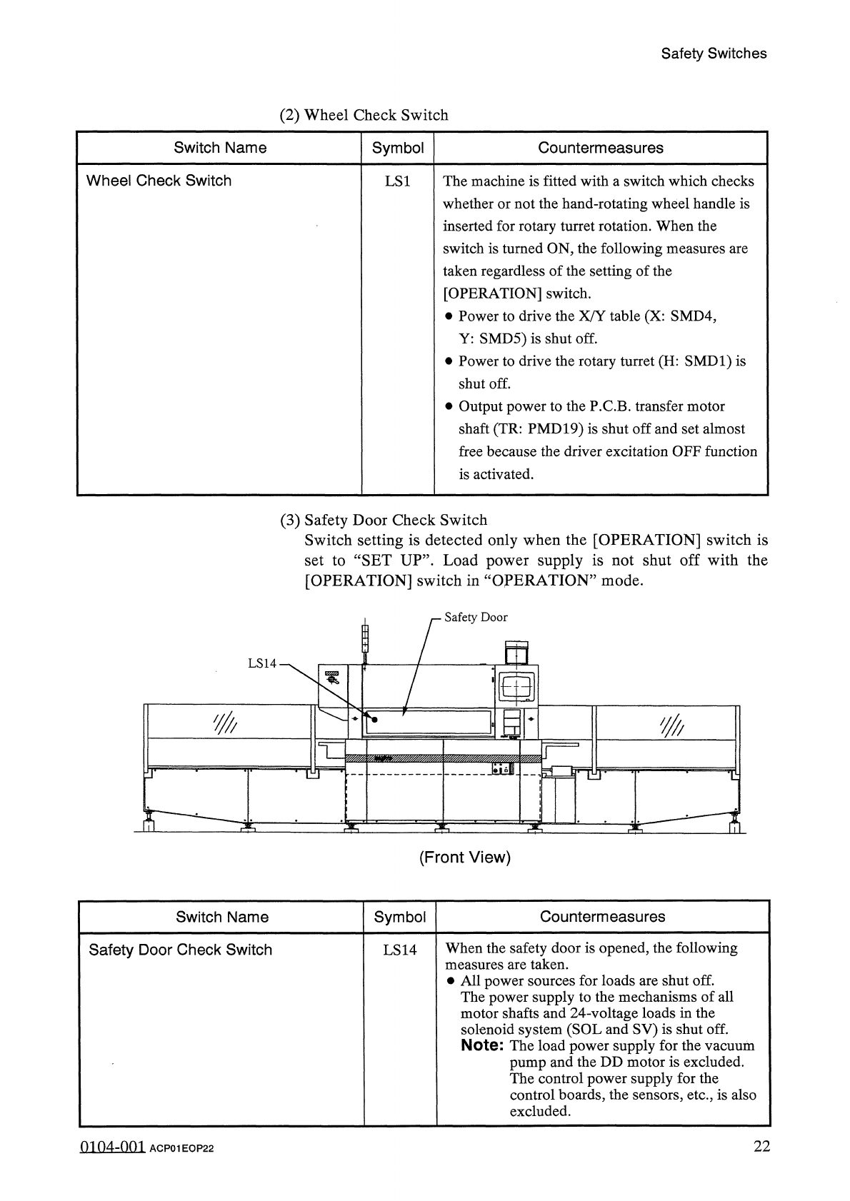
3
)
Safety
Door
Check
Switch
Switch
setting
is
detected
only
when
the
[
OPERATION
]
switch
is
set
to
“
SET
UP
”
.
Load
power
supply
is
not
shut
off
with
the
[
OPERATION
]
switch
in
“
OPERATION
”
mode
.
Safety
Door
m
LS
14
wmmm
mm
-
TO
-
(
Front
View
)
Co
u
nte
rmeasu
res
Switch
Name
Symbol
When
the
safety
door
is
opened
,
the
following
measures
are
taken
.
•
All
power
sources
for
loads
are
shut
off
.
The
power
supply
to
the
mechanisms
of
all
motor
shafts
and
24
-
voltage
loads
in
the
solenoid
system
(
SOL
and
SV
)
is
shut
off
.
Note
:
The
load
power
supply
for
the
vacuum
pump
and
the
DD
motor
is
excluded
.
The
control
power
supply
for
the
control
boards
,
the
sensors
,
etc
.
,
is
also
excluded
.
Safety
Door
Check
Switch
LS
14
22
mn
4
-
nm
ACP
01
EOP
22