1OPERATION_.pdf - 第283页
5.5 Manual Subsystem Operation ① [ INDEX THE TURRET ( + ) ] , [ INDEX THE TURRET ( - ) ] The rotary turret is rotated by 1 pitch in the normal ( + ) or reverse ( 一 ) direction . ② [ CYCLE THE TURRET ( + ) HIGH SPEED ] , …
5.5
Manual
Subsystem
Operation
[
NEXT
PAGE
]
[
PREY
PAGE
]
(
Fourth
Page
)
04
/
06
m
Eg
:
!
N
STATUS
DEVICE
NAME
NU
250
L
3
OFF
-
ON
OFF
-
ON
OFF
-
ON
OFF
-
ON
OFF
-
ON
OFF
-
ON
OFF
-
ON
OFF
-
ON
DFF
HEAD
II
VACUUM
VALVE
1
OFF
HEAD
12
VACUUM
VALVE
MANUAL
OFF
HEAD
13
VACUUM
VALVE
OFF
HEAD
14
VACUUM
VALVE
OFF
.
HEAD
IS
VACUUM
VALVE
OFF
HEAD
t
6
VACUUM
VALVE
1
OF
-
F
HEAD
17
VACUUM
VALVE
1
OFF
HEAD
88
VACUUM
VALVE
NP
^
E
PP
^
E
SELECT
THE
OPTION
&
PRESS
THE
IWM
]
BUTTON
.
Fig
.
5.5
-
4
[
NEXT
PAGE
]
[
PREY
PAGE
]
(
Fifth
Page
)
05
/
06
^
MENU
?
5
Qll
STATUS
DEVICE
NAME
1
OFF
-
ON
OFF
-
ON
OFF
-
ON
OFF
-
ON
OFF
-
ON
OFF
-
ON
OFF
-
ON
OFF
-
ON
OFF
HEAD
19
VACUUM
VALVE
MANUA
M
3
OFF
HEAD
«
10
VACUUM
VALVE
mm
MANUAL
HEAD
111
VACUUM
VALVE
;
,
.
OFF
1
妍
HEAD
«
12
VACUUM
VALVE
1
OFF
HEAD
113
VACUUM
VALVE
OFF
HEAD
»
4
VACUUM
VALVE
OFF
HEAD
115
VACUUM
VALVE
OFF
HEAD
«
16
VACUUM
VALVE
SELECT
THE
OPTION
1
PRESS
THE
[
MOVE
]
BUTTON
.
Fig
.
5.5
-
5
[
PREY
PAGE
]
[
NEXT
PAGE
]
(
Sixth
Page
)
06
/
06
m
N
DEVICE
NAME
STATUS
NU
250
INPUT
CONVEYOR
(
f
)
OFF
OFF
-
ON
OFF
-
ON
OFF
-
ON
:
OFF
-
ON
:
OFF
-
ON
OFF
_
ON
OFF
-
ON
MANUA
INPUT
CONVEYOR
H
OFF
IH
MANUAL
INPUT
BUFFER
CjyEYORJj
]
OFF
INPUT
BUFFER
CONVEYOR
P
.
C
.
8
.
STOP
OFF
ON
OUTPUT
CONVEYOR
(
t
)
OFF
OUTPUT
CONVEYOR
P
.
C
.
B
.
STOP
OUTPUT
CONVEYOR
H
OFF
SELECT
THE
CPTION
&
PRESS
M
[
MDVE
1
BUTTON
.
Fig
.
5.5
-
6
5
-
8
Qsn
^
-
nm
ACP
01
EOP
5
-
8
5.5
Manual
Subsystem
Operation
①
[
INDEX
THE
TURRET
(
+
)
]
,
[
INDEX
THE
TURRET
(
-
)
]
The
rotary
turret
is
rotated
by
1
pitch
in
the
normal
(
+
)
or
reverse
(
一
)
direction
.
②
[
CYCLE
THE
TURRET
(
+
)
HIGH
SPEED
]
,
[
CYCLE
THE
TURRET
(
+
)
MIDDLE
SPEED
]
,
[
CYCLE
THE
TURRET
(
+
)
LOW
SPEED
]
,
[
CYCLE
THE
TURRET
(
-
)
HIGH
SPEED
]
,
[
CYCLE
THE
TURRET
(
-
}
MIDDLE
SPEED
]
,
[
CYCLE
THE
TURRET
(
—
)
LOW
SPEED
]
,
The
rotary
turret
is
rotated
smoothly
in
the
normal
(
+
)
or
reverse
(
一
)
direction
at
high
,
middle
,
or
low
speed
.
③
[
FEEDER
INDEX
#
1
CLUTCH
(
260
°
-
320
°
)
]
The
tape
feed
clutch
is
turned
ON
or
OFF
.
When
the
clutch
is
turned
ON
,
it
is
activated
in
the
range
of
turret
angle
260
°
④
[
FEEDER
INDEX
#
2
CLUTCH
(
40
°
-
120
°
)
]
,
-
320
.
[
FEEDER
INDEX
#
5
CLUTCH
(
40
°
—
120
°
)
]
,
The
tape
index
clutch
of
the
tape
feeder
located
at
each
pitch
position
is
turned
ON
or
OFF
.
When
the
clutch
is
turned
ON
,
it
is
activated
in
the
range
of
turret
angle
40
⑤
[
FEEDER
SHUTTER
CLUTCH
(
40
°
-
120
°
)
]
[
FEEDER
COVER
TAPE
CLUTCH
(
40
°
-
120
°
)
]
[
NOZZLE
UP
-
POSITION
CLUTCH
(
40
°
—
120
°
)
]
[
NOZZLE
DOWN
-
POSITION
CLUTCH
(
40
°
-
120
°
)
]
[
NOZZLE
MIDDLE
-
POSITION
CLUTCH
(
40
°
-
120
°
)
]
[
COMPONENT
PICK
-
UP
CLUTCH
(
40
°
—
120
°
)
]
[
COMPONENT
PLACEMENT
CLUTCH
(
40
°
-
120
°
)
]
Each
clutch
is
turned
ON
or
OFF
.
When
the
clutch
is
turned
ON
,
it
is
activated
in
the
range
of
turret
angle
40
°
—
120
°
.
一
120
.
⑥
[
TRANSFER
(
CYCLE
)
]
[
TRANSFER
(
STEP
)
]
The
P
.
C
.
B
.
transfer
is
moved
1
cycle
or
by
1
step
.
1
-
cycle
operation
of
the
P
.
C
.
B
.
transfer
means
that
a
P
.
C
.
B
.
is
transferred
onto
the
X
/
Y
table
or
a
P
.
C
.
B
.
on
the
X
/
Y
table
is
discharged
onto
the
output
conveyor
.
1
-
Step
Operation
of
P
.
C
.
B
.
Transfer
:
Downward
Movement
—
Claw
—
Returning
of
Transfer
Claw
(
When
the
[
MOVE
]
button
is
pressed
,
the
transfer
is
activated
by
1
step
.
)
Note
:
The
P
.
C
.
B
,
transfer
(
cycle
)
operation
cannot
be
performed
with
the
[
OPERATION
/
SET
UP
]
switch
set
to
the
“
SET
UP
”
side
.
9803
-
001
ACP
01
EOP
5
-
9
5
—
9
5.5
Manual
Subsystem
Operation
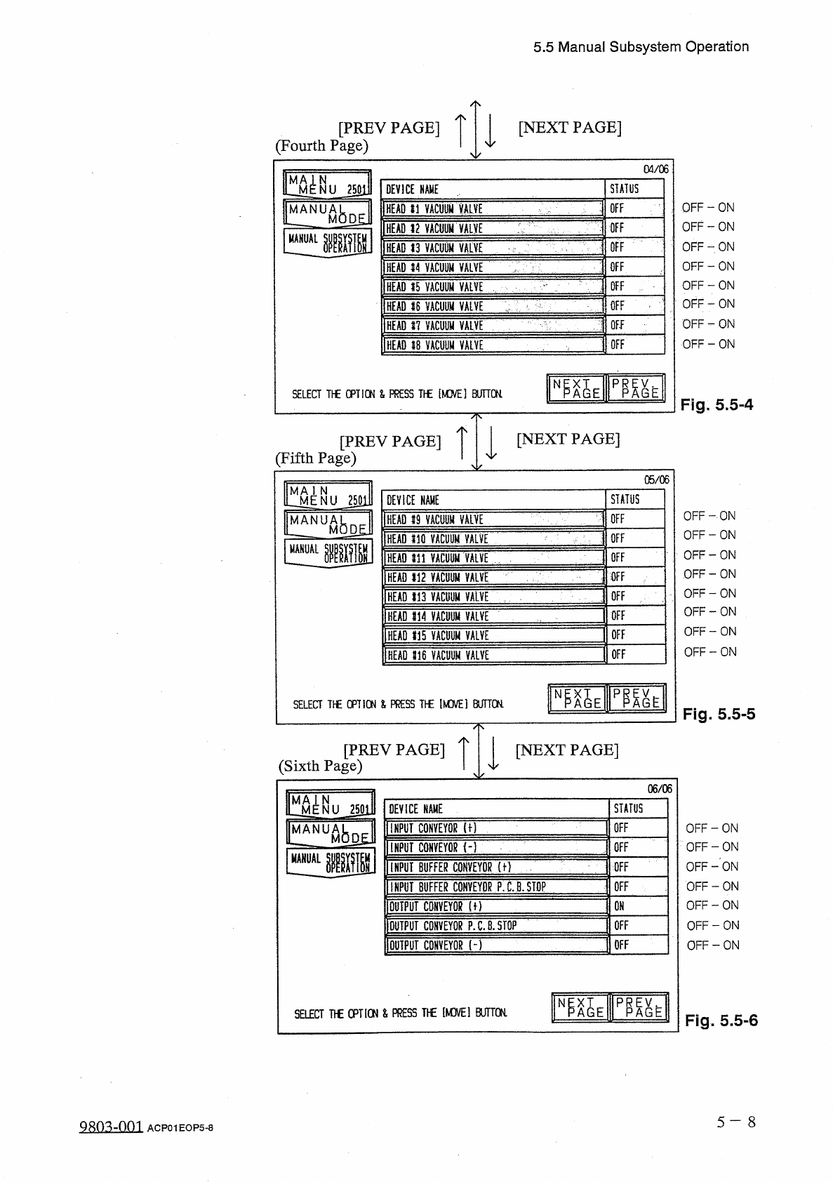
⑦
[
HEAD
#
1
VACUUM
VALVE
]
,
[
HEAD
#
16
VACUUM
VALVE
]
The
vacuum
valves
of
head
#
s
1
~
16
are
turned
ON
or
OFF
.
ON
:
Vacuum
is
shut
off
.
OFF
:
Vacuum
is
supplied
.
⑧
[
INPUT
CONVEYOR
(
+
)
]
,
[
INPUT
CONVEYOR
㈠
]
The
input
conveyor
is
rotated
in
the
normal
or
reverse
direction
.
⑨
[
INPUT
BUFFER
CONVEYOR
(
+
)
]
The
input
buffer
conveyor
is
rotated
in
the
normal
direction
.
⑩
[
INPUT
BUFFER
CONVEYOR
P
.
C
.
B
.
STOP
]
The
input
buffer
conveyor
stopper
is
turned
ON
or
OFF
.
⑪
[
OUTPUT
CONVEYOR
(
+
)
]
,
[
OUTPUT
CONVEYOR
(
—
)
]
The
output
conveyor
is
rotated
in
the
normal
or
reverse
direction
.
⑫
[
OUTPUT
CONVEYOR
P
.
C
.
B
.
STOP
]
The
output
conveyor
stopper
is
turned
ON
or
OFF
.
•
Select
the
device
to
be
moved
manually
and
press
the
[
MOVE
]
button
.
•
When
the
rotary
turret
or
the
P
.
C
.
B
.
transfer
is
selected
,
1
-
cycle
or
1
-
step
operation
of
the
turret
or
the
transfer
is
performed
every
time
the
[
MOVE
]
button
is
pressed
.
After
1
-
cycle
or
1
-
step
operation
,
the
selected
device
stops
.
•
When
each
stopper
or
head
vacuum
valve
is
selected
,
the
selected
device
is
turned
ON
or
OFF
every
time
the
[
MOVE
]
button
is
pressed
.
5
—
10
Q
廳
-
om
ACP
01
EOP
5
-
10