1OPERATION_.pdf - 第53页
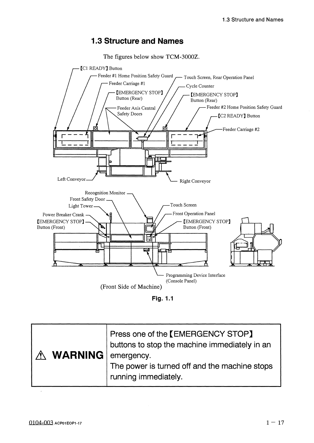
1.3 Structure and Names 1.3 Structure and Names The figures below show TCM - 3000 Z . [ Cl READY 】 Button Feeder # 1 Home Position Safety Guard Feeder Carriage # 1 / Touch Screen , Rear Operation Panel 一 Cycle Counter 【 …
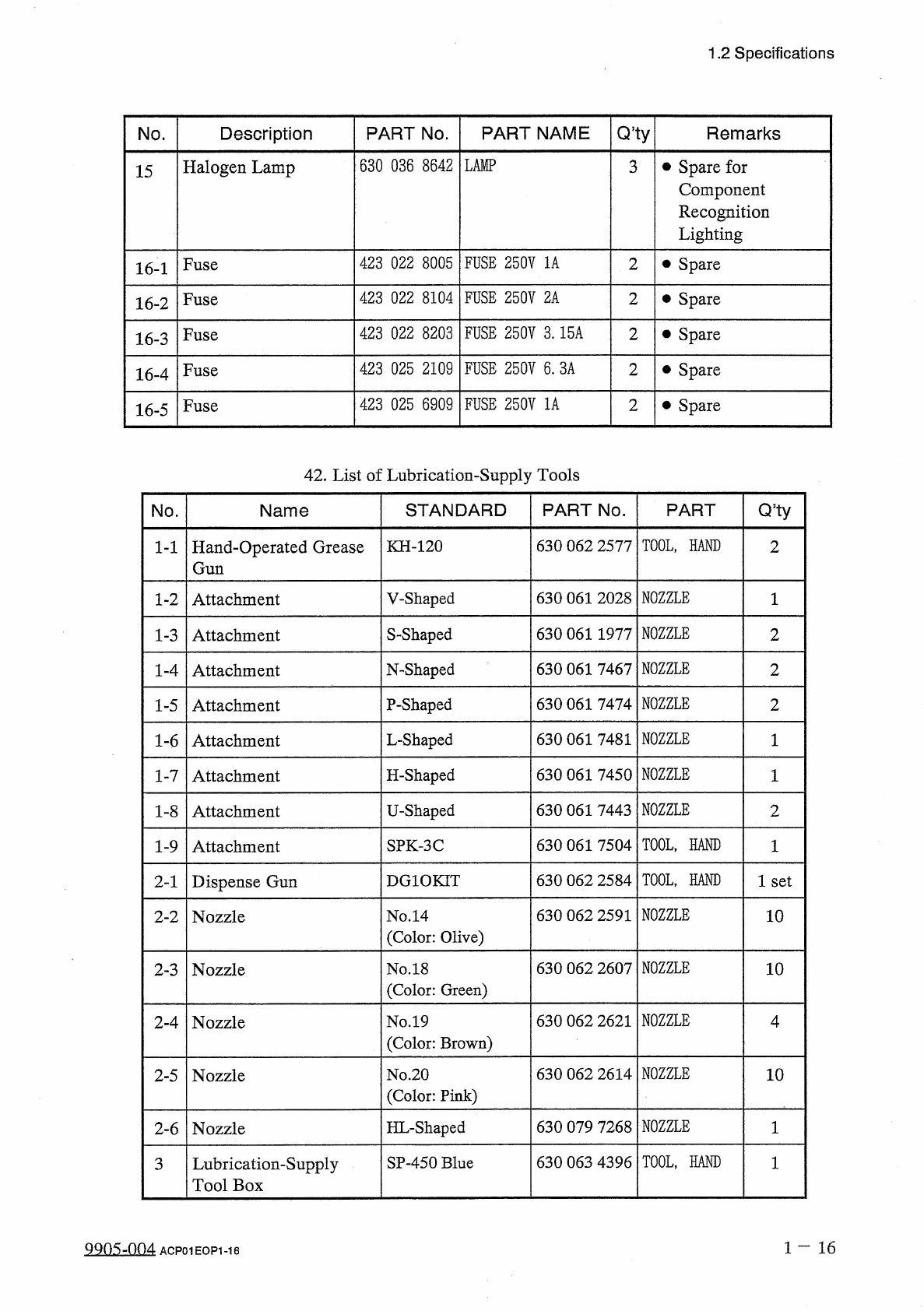
1.2
Specifications
Q
,
ty
PART
NAME
PART
No
.
Remarks
No
.
Description
630
036
8642
LAMP
•
Spare
for
Component
Recognition
Lighting
Halogen
Lamp
3
15
FUSE
250
V
1
A
423
022
8005
2
•
Spare
Fuse
16
-
1
423
022
8104
FUSE
250
V
2
A
2
•
Spare
Fuse
16
-
2
FUSE
250
V
3.15
A
423
022
8203
2
•
Spare
Fuse
16
-
3
423
025
2109
FUSE
250
V
6
.
3
A
2
•
Spare
Fuse
16
-
4
423
025
6909
FUSE
250
V
1
A
2
•
Spare
Fuse
16
-
5
42
.
List
of
Lubrication
-
Supply
Tools
Q
5
ty
STANDARD
PART
No
.
PART
No
.
Name
TOOL
,
HAND
630
062
2577
KH
-
120
Hand
-
Operated
Grease
Gun
2
1
-
1
NOZZLE
630
061
2028
V
-
Shaped
Attachment
1
1
-
2
NOZZLE
S
-
Shaped
630
061
1977
2
1
-
3
Attachment
NOZZLE
630
061
7467
N
-
Shaped
2
1
-
4
Attachment
NOZZLE
P
-
Shaped
630
061
7474
2
1
-
5
Attachment
NOZZLE
630
061
7481
L
-
Shaped
1
-
6
Attachment
1
NOZZLE
H
-
Shaped
630
061
7450
1
1
-
7
Attachment
NOZZLE
630
061
7443
U
-
Shaped
2
1
-
8
Attachment
TOOL
,
HAND
630
061
7504
SPK
-
3
C
1
1
-
9
Attachment
TOOL
,
HAND
630
062
2584
DG
10
KIT
1
set
Dispense
Gun
2
-
1
NOZZLE
630
062
2591
No
.
14
(
Color
:
Olive
)
10
Nozzle
2
-
2
NOZZLE
630
062
2607
10
No
.
18
(
Color
:
Green
)
2
-
3
Nozzle
NOZZLE
630
062
2621
No
.
19
(
Color
:
Brown
)
4
Nozzle
2
-
4
NOZZLE
630
062
2614
No
.
20
(
Color
:
Pink
)
10
2
-
5
Nozzle
NOZZLE
HL
-
Shaped
630
079
7268
1
2
-
6
Nozzle
TOOL
,
HAND
630
063
4396
SP
-
450
Blue
Lubrication
-
Supply
Tool
Box
3
1
-
16
叫
05
-
004
ACP
01
EOP
1
-
16
1.3
Structure
and
Names
1.3
Structure
and
Names
The
figures
below
show
TCM
-
3000
Z
.
[
Cl
READY
】
Button
Feeder
#
1
Home
Position
Safety
Guard
Feeder
Carriage
#
1
/
Touch
Screen
,
Rear
Operation
Panel
一
Cycle
Counter
【
EMERGENCY
STOP
]
Button
(
Rear
)
【
EMERGENCY
STOP
]
Button
(
Rear
)
Feeder
#
2
Home
Position
Safety
Guard
Feeder
Axis
Central
Safety
Doors
/
[
C
2
READY
]
Button
■
Feeder
Carriage
#
2
o
Left
Conveyor
Right
Conveyor
Recognition
Monitor
Front
Safety
Door
Light
Tower
Touch
Screen
Front
Operation
Panel
[
EMERGENCY
STOP
]
Button
(
Front
)
Power
Breaker
Crank
【
EMERGENCY
STOP
]
Button
(
Front
)
n
a
%
-
^
?
i
S
:
Programming
Device
Interface
(
Console
Panel
)
(
Front
Side
of
Machine
)
Fig
.
1.1
Press
one
of
the
【
EMERGENCY
STOP
】
buttons
to
stop
the
machine
immediately
in
an
emergency
.
The
power
is
turned
off
and
the
machine
stops
running
immediately
.
A
WARNING
0104
-
003
1
-
17
ACP
01
EOP
1
-
17
1.4
Operation
Panel
1.4
Operation
Panel
1.4
.
1
Power
Breaker
Crank
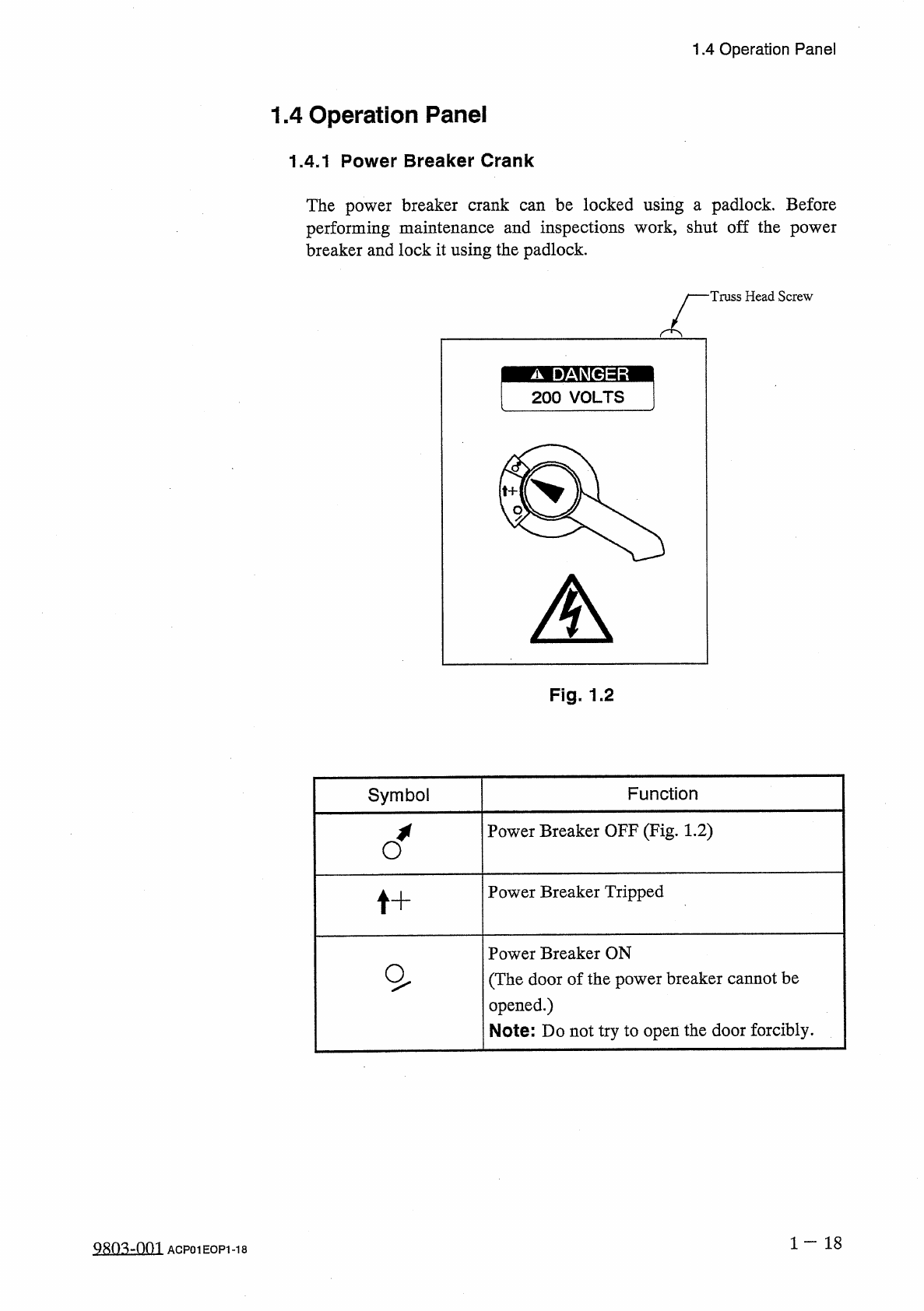
The
power
breaker
crank
can
be
locked
using
a
padlock
.
Before
performing
maintenance
and
inspections
work
,
shut
off
the
power
breaker
and
lock
it
using
the
padlock
.
Truss
Head
Screw
Fig
.
1.2
Symbol
Function
Power
Breaker
OFF
(
Fig
.
1.2
)
Power
Breaker
Tripped
t
+
Power
Breaker
ON
(
The
door
of
the
power
breaker
cannot
be
opened
.
)
Note
:
Do
not
try
to
open
the
door
forcibly
.
1
一
18
Q
803
-
0
m
ACP
01
EOP
1
-
18