1OPERATION_.pdf - 第178页
4.2 “ AUTO OPN . MODE 〈 PLACEMENT 〉 ” Display ⑥ When this key is pressed , the “ MAIN MENU ” display appears the screen . on ⑦ Normally the key is labeled as follows . AUTO OPN . MODE I AUTO OPN . MODE < PLACEMENT >…
本 窣 本 本 本
ORIGIN
MOH
TOR
%
%
%
%
%
[
SCREENS
miFmm
STOP
m p
«
8
:
<
P
.
C
.
B
.
COUNTER
>
PROS
.
腿
8
PROD
.
1
<
P
.
C
.
B
.
PRCS
.
TIME
>
’
30
0
SEC
.
CLEAR
THE
N
NU
100
°
»
i
IUT
0
s
8
fe
MGT
INFO
.
4.2
“
AUTO
OPN
.
MODE
<
PLACEMENT
>
"
Display
4.2
“
AUTO
OPN
.
MODE
<
PLACEMENT
>
”
Display
When
the
[
AUTO
OPN
MODE
]
key
is
pressed
at
the
“
MAIN
MENU
:
display
,
the
following
display
appears
on
the
screen
.
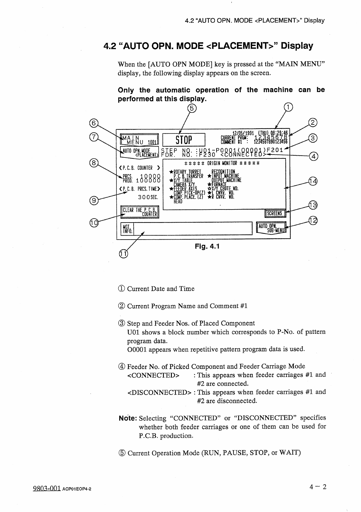
Only
the
automatic
operation
of
the
machine
can
be
performed
at
this
display
.
5
6
2
7
O
8
(
14
)
03
)
do
)
Fig
.
4.1
①
Current
Date
and
Time
②
Current
Program
Name
and
Comment
#
1
③
Step
and
Feeder
Nos
.
of
Placed
Component
UOl
shows
a
block
number
which
corresponds
to
P
-
No
.
of
pattern
program
data
.
OOOOl
appears
when
repetitive
pattern
program
data
is
used
.
④
Feeder
No
.
of
Picked
Component
and
Feeder
Carriage
Mode
:
This
appears
when
feeder
carriages
#
1
and
#
2
are
connected
.
〈
DISCONNECTED
〉
:
This
appears
when
feeder
carriages
#
1
and
#
2
are
disconnected
.
<
CONNECTED
>
DISCONNECTED
”
specifies
Note
:
Selecting
whether
both
feeder
carriages
or
one
of
them
can
be
used
for
P
.
C
.
B
.
production
.
CONNECTED
:
or
⑤
Current
Operation
Mode
(
RUN
,
PAUSE
,
STOP
,
or
WAIT
)
4
一
2
aSQSzQQJ
ACP
01
EOP
4
-
2
nMAMEUT
:
SH
-
從
CHVRVR
-
ER
Rs
CJU
RN
Y
[
-
E
UAE
/
XKC
TAK
—
-
XACA
TB
I
Y
.
AADftrp
RODTRE
-
.
A
EnuppD
-
—
CYMEMMA
o
.
/
AEQOE
RPXA
-
v
-
rccH
4.2
“
AUTO
OPN
.
MODE
〈
PLACEMENT
〉
”
Display
⑥
When
this
key
is
pressed
,
the
“
MAIN
MENU
”
display
appears
the
screen
.
on
⑦
Normally
the
key
is
labeled
as
follows
.
AUTO
OPN
.
MODE
I
AUTO
OPN
.
MODE
<
PLACEMENT
>
|
<
PASSED
>
|
Do
not
perform
automatic
operation
when
the
status
is
labeled
as
“
DEVICE
TEST
,,
.
Normal
automatic
operation
cannot
be
performed
because
test
mode
data
is
set
.
A
CAUTION
:
<
PLACEMENT
>
”
or
“
<
PASSED
>
”
simply
shows
the
status
of
vacuum
pump
and
blower
motor
.
〈
PLACEMENT
〉
:
Vacuum
pump
and
blower
motor
are
ON
.
<
PASSED
>
:
Vacuum
pump
and
blower
motor
are
OFF
.
⑧
"
P
.
C
.
B
.
COUNTER
”
Both
single
-
and
multi
-
unit
P
.
C
.
B
/
s
are
counted
when
specified
in
the
pattern
program
data
.
Single
-
Unit
P
.
C
.
B
.
:
Normally
the
counter
counts
up
in
increments
of
one
P
.
C
.
B
.
in
the
pattern
program
data
and
the
repetitive
pattern
program
data
.
Multi
-
Unit
P
.
C
.
B
.
:
The
counter
counts
up
the
number
of
actually
placed
multi
-
unit
P
.
C
.
B
.
’
s
.
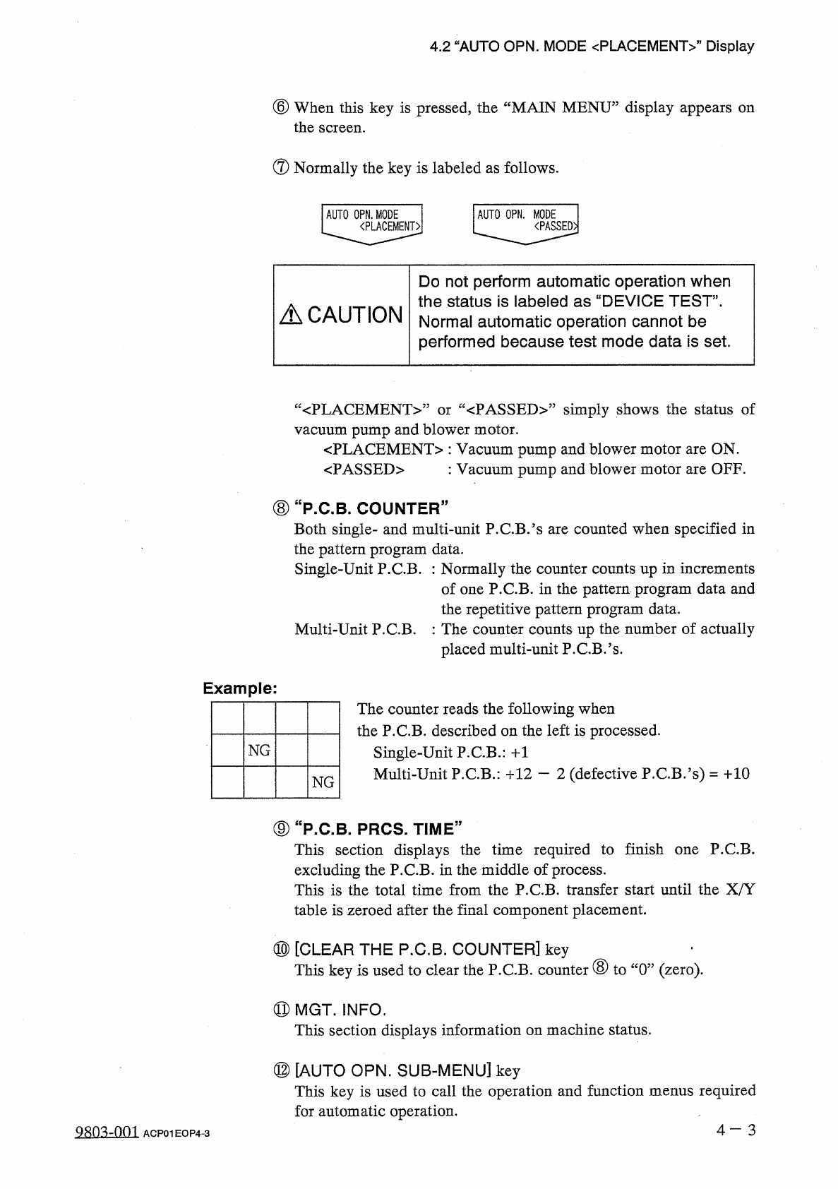
Example
:
The
counter
reads
the
following
when
the
P
.
C
.
B
.
described
on
the
left
is
processed
.
Single
-
Unit
P
.
C
.
B
.
:
+
1
Multi
-
Unit
P
.
C
.
B
.
:
十
12
—
2
(
defective
P
.
C
.
B
.
’
s
)
=
十
10
NG
NG
⑨
“
P
.
C
.
B
_
PRCS
.
TIME
”
This
section
displays
the
time
required
to
finish
one
P
.
C
.
B
.
excluding
the
P
.
C
.
B
.
in
the
middle
of
process
.
This
is
the
total
time
from
the
P
.
C
.
B
.
transfer
start
until
the
X
/
Y
table
is
zeroed
after
the
final
component
placement
.
⑩
[
CLEAR
THE
P
.
C
.
B
.
COUNTER
]
key
This
key
is
used
to
clear
the
P
.
C
.
B
.
counter
⑧
to
“
0
”
(
zero
)
.
⑪
MGT
.
INFO
.
This
section
displays
information
on
machine
status
.
⑫
[
AUTO
OPN
.
SUB
-
MENU
]
key
This
key
is
used
to
call
the
operation
and
function
menus
required
for
automatic
operation
.
4
一
3
0803
=
001
ACP
01
EOP
4
-
3
4.2
“
AUTO
OPN
.
MODE
<
PLACEMENT
>
”
Display
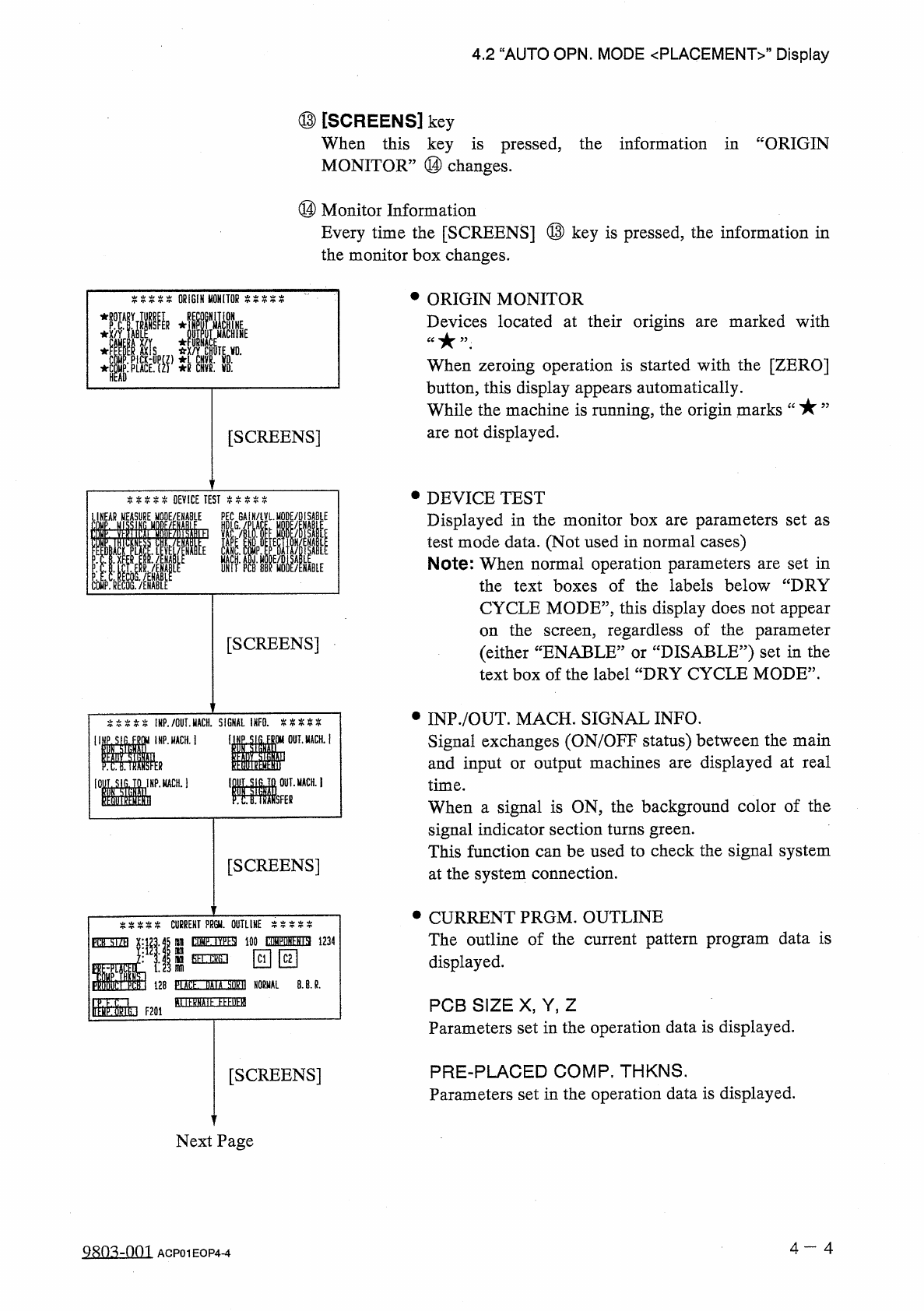
⑬
[
SCREENS
]
key
When
this
key
is
pressed
,
the
information
in
“
ORIGIN
MONITOR
”
⑭
changes
.
⑭
Monitor
Information
Every
time
the
[
SCREENS
]
⑬
key
is
pressed
,
the
information
in
the
monitor
box
changes
.
•
ORIGIN
MONITOR
Devices
located
at
their
origins
are
marked
with
ORIGIN
MONITOR
E
:
i
When
zeroing
operation
is
started
with
the
[
ZERO
]
button
,
this
display
appears
automatically
.
While
the
machine
is
running
,
the
origin
marks
are
not
displayed
.
[
SCREENS
]
•
DEVICE
TEST
Displayed
in
the
monitor
box
are
parameters
set
as
test
mode
data
.
(
Not
used
in
normal
cases
)
Note
:
When
normal
operation
parameters
are
set
in
the
text
boxes
of
the
labels
below
“
DRY
%
%
%
%
%
DEVICE
TEST
P
COMP
.
RECOG
.
/
ENABLE
LINEAR
MODE
/
ENABLE
HDLG
GAIN
/
iVLMQDE
/
DISABlE
CYCLE
MODE
”
,
this
display
does
not
appear
the
screen
,
regardless
of
the
parameter
:
DISABLE
?
?
)
set
in
the
on
[
SCREENS
]
(
either
“
ENABLE
:
text
box
of
the
label
“
DRY
CYCLE
MODE
”
.
or
•
INP
.
/
OUT
.
MACH
.
SIGNAL
INFO
.
Signal
exchanges
(
ON
/
OFF
status
)
between
the
main
and
input
or
output
machines
are
displayed
at
real
time
.
When
a
signal
is
ON
,
the
background
color
of
the
signal
indicator
section
turns
green
.
This
function
can
be
used
to
check
the
signal
system
at
the
system
connection
.
%
%
%
%
%
!
HP
.
/
OUT
.
MACH
.
SIGNAL
INFO
.
%
%
%
%
%
INP
.
MACH
.
j
醒
。
_
ii
IDf
.
SIG
.
TO
IMP
.
MCH
.
1
MM
[
SCREENS
]
•
CURRENT
PRGM
.
OUTLINE
The
outline
of
the
current
pattern
program
data
is
displayed
.
CURRENT
PPGU
.
OUTLINE
tOMF
.
IV
^
SI
100
WuN
^
ia
1234
fih
.
ckG
.
i
PflH
■
X
nn
回回
sm
128
PLACL
DAIA
M
NORMAL
8
.
B
.
R
.
B
USSDE
EEEBEfl
Ir
^
CTikt
F
20
i
PCB
SIZE
X
,
Y
,
Z
Parameters
set
in
the
operation
data
is
displayed
.
PRE
-
PLACED
COMP
.
THKNS
.
Parameters
set
in
the
operation
data
is
displayed
.
[
SCREENS
]
Next
Page
4
一
4
Q
8
n
^
-
001
ACP
01
EOP
4
-
4