1OPERATION_.pdf - 第77页
1.8 Placement Head Section 1.8 Placement Head Section 16 heads are attached to the turntable and each head can accommodate 5 types of nozzles . Nozzle Position # 5 Nozzle Position # 4 Nozzle Position # 1 ( Top View ) <…
Max
.
160
kg
/
carriage
Max
.
215
kg
/
carriage
80
-
Lane
Mode
160
-
Lane
Mode
(
2
Feeder
Carriages
)
Max
.
215
kg
/
carriage
(
Max
.
320
kg
on
two
carriages
)
(
Max
.
430
kg
on
two
carriages
)
Max
.
160
kg
/
carriage
40
-
Lane
Mode
Max
.
108
kg
/
carriage
80
-
Lane
Mode
(
2
Feeder
Carriages
)
Max
.
108
kg
/
carriage
(
Max
.
216
kg
on
two
carriages
)
Ref
.
:
Approx
.
Weight
of
8
mm
Tape
Feeder
(
1
pc
.
)
•
Tape
Feeder
with
Small
Reel
Holder
:
1.33
kg
(
1
,
175
g
(
Main
Body
)
+
150
g
(
Tape
Reel
Holder
)
)
•
Tape
Feeder
with
Large
Reel
Holder
:
2.69
kg
(
2
,
150
g
(
Main
Body
)
+
540
g
(
Tape
Reel
Holder
)
)
The
above
approximate
weights
are
average
ones
when
main
components
are
taped
and
vary
according
to
the
components
being
used
.
Notes
:
(
a
)
When
the
“
80
+
30
(
40
+
40
)
-
Lane
Mode
”
is
set
,
feeder
not
connected
but
work
carriages
#
1
and
#
2
together
in
harmony
.
(
b
)
The
underlined
feeder
Nos
.
in
(
)
apply
to
TCM
-
3100
J
.
are
(
5
)
Bulk
Feeders
Any
pneumatic
bulk
feeders
cannot
be
used
.
If
a
pneumatic
bulk
feeder
is
set
to
the
component
supply
section
,
the
air
supply
section
will
touch
and
damage
the
linear
measure
detection
sensor
.
1
一
38
9
Sn
3
-
0
ni
ACP
01
EOP
1
-
38
1.7
Installation
of
Tape
Feeders
on
Feeder
Carriages
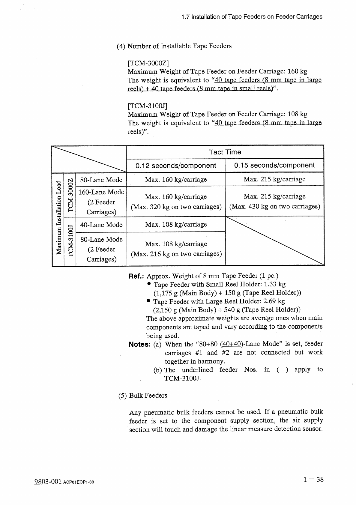
(
4
)
Number
of
Installable
Tape
Feeders
[
TCM
-
3000
Z
]
Maximum
Weight
of
Tape
Feeder
on
Feeder
Carriage
:
160
kg
The
weight
is
equivalent
to
“
40
tape
feeders
(
8
reels
)
+
4
-
0
tape
feeder
只
(
8
tap
tape
in
small
[
TCM
-
3100
J
]
Maximum
Weight
of
Tape
Feeder
on
Feeder
Carriage
:
108
kg
The
weight
is
equivalent
to
“
40
tape
feeders
(
8
tape
in
large
Tact
Time
0.15
seconds
/
component
0.12
seconds
/
component
PBOq
uopJSlBsal
sn
日
JXcdIAI
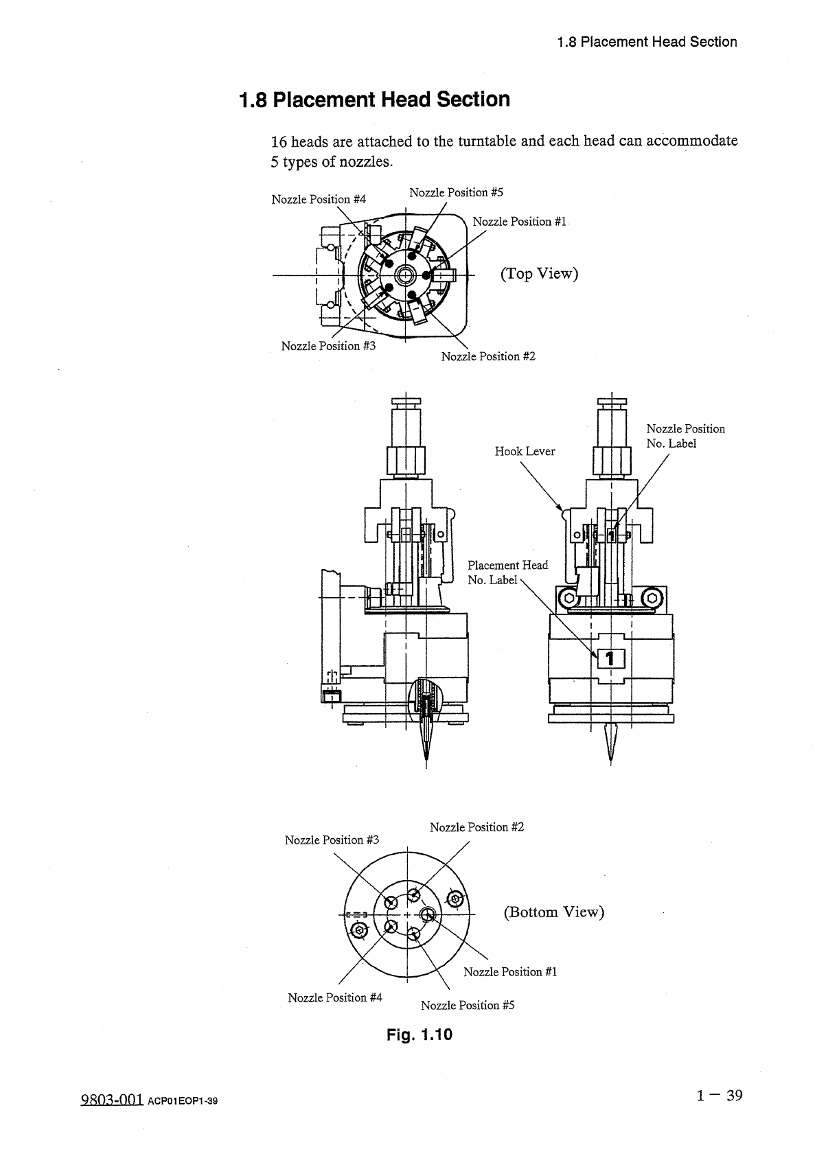
1.8
Placement
Head
Section
1.8
Placement
Head
Section
16
heads
are
attached
to
the
turntable
and
each
head
can
accommodate
5
types
of
nozzles
.
Nozzle
Position
#
5
Nozzle
Position
#
4
Nozzle
Position
#
1
(
Top
View
)
<
Nozzle
Position
#
3
Nozzle
Position
#
2
Nozzle
Position
No
.
Label
Hook
Lever
Placement
Head
No
.
Label
\
-
m
]
Hi
]
V
Nozzle
Position
#
2
Nozzle
Position
#
3
(
Bottom
View
)
Nozzle
Position
#
1
Nozzle
Position
#
4
Nozzle
Position
#
5
Fig
.
1.10
1
一
39
QRO
^
-
nm
ACP
01
EOP
1
-
39
1.8
Placement
Head
Section
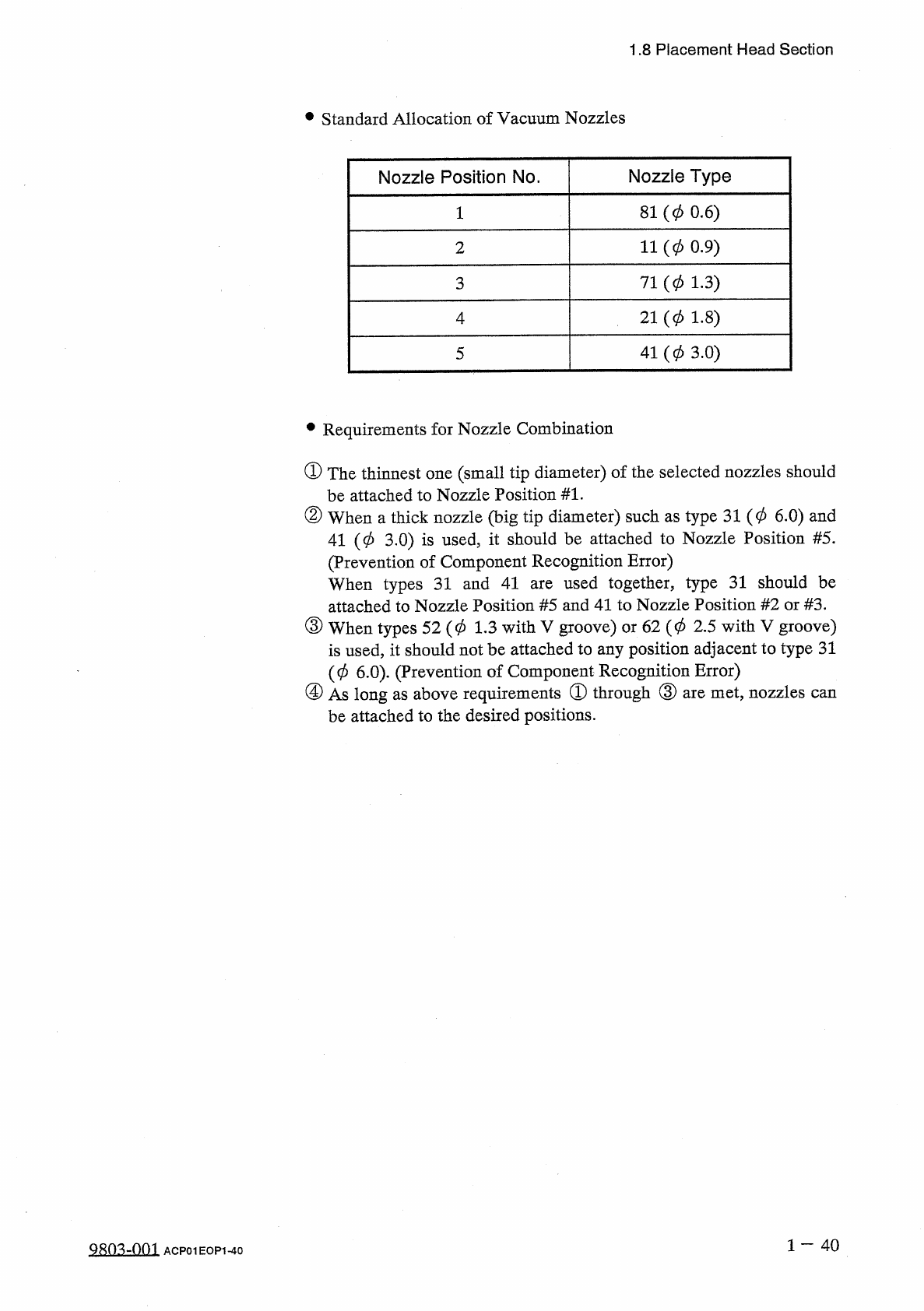
•
Standard
Allocation
of
Vacuum
Nozzles
Nozzle
Position
No
.
Nozzle
Type
81
(
0
0.6
)
11
(
0
0.9
)
2
71
(
0
1.3
)
3
21
(
0
1.8
)
4
41
(
0
3.0
)
5
•
Requirements
for
Nozzle
Combination
①
The
thinnest
one
(
small
tip
diameter
)
of
the
selected
nozzles
should
be
attached
to
Nozzle
Position
#
1
.
②
When
a
thick
nozzle
(
big
tip
diameter
)
such
as
type
31
(
0
6.0
)
and
41
(
0
3.0
)
is
used
,
it
should
be
attached
to
Nozzle
Position
#
5
.
(
Prevention
of
Component
Recognition
Error
)
When
types
31
and
41
attached
to
Nozzle
Position
#
5
and
41
to
Nozzle
Position
#
2
or
#
3
.
③
When
types
52
(
0
1.3
with
V
groove
)
or
62
(
0
2.5
with
V
groove
)
is
used
,
it
should
not
be
attached
to
any
position
adjacent
to
type
31
(
0
6.0
)
.
(
Prevention
of
Component
Recognition
Error
)
④
As
long
as
above
requirements
®
through
③
are
met
,
nozzles
be
attached
to
the
desired
positions
.
used
together
,
type
31
should
be
are
can
1
—
40
9803
-
001
ACP
01
EOP
1
-
40