1OPERATION_.pdf - 第52页
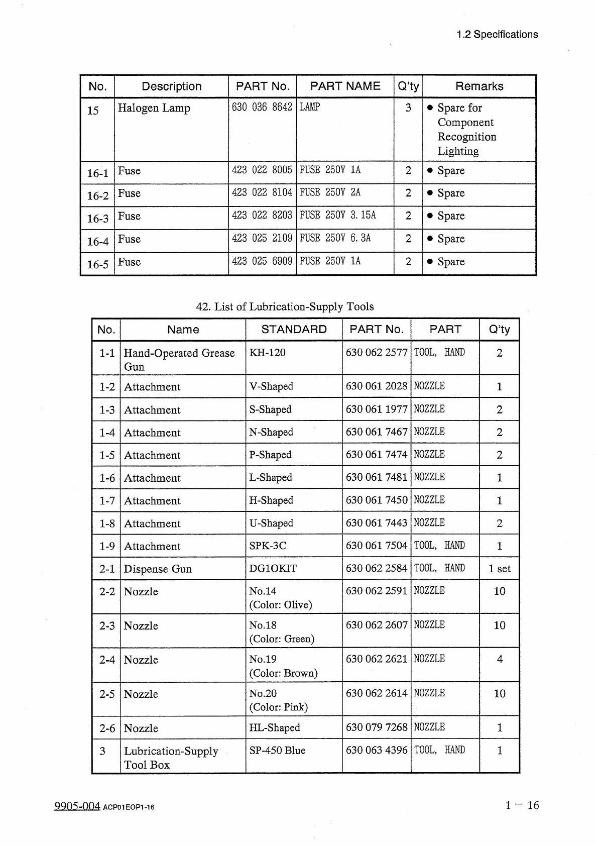
1.2 Specifications Q , ty PART NAME PART No . Remarks No . Description 630 036 8642 LAMP • Spare for Component Recognition Lighting Halogen Lamp 3 15 FUSE 250 V 1 A 423 022 8005 2 • Spare Fuse 16 - 1 423 022 8104 FUSE 25…
1.2
Specifications
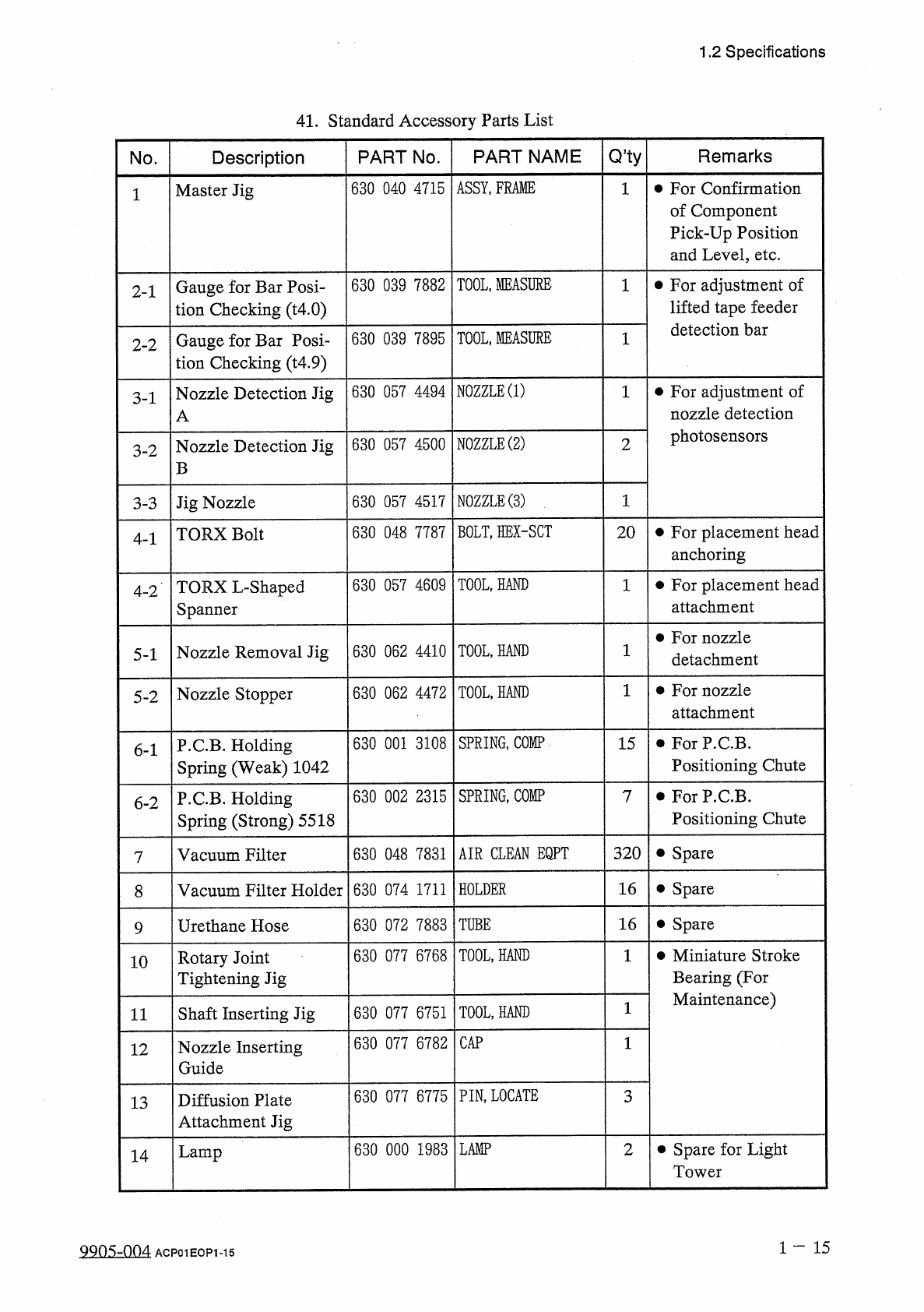
41
.
Standard
Accessory
Parts
List
Q
,
ty
PART
NAME
Remarks
No
.
Description
PART
No
.
ASSY
,
FRAME
630
040
4715
•
For
Confirmation
of
Component
Pick
-
Up
Position
and
Level
,
etc
.
1
Master
Jig
1
TOOL
,
MEASURE
630
039
7882
•
For
adjustment
of
lifted
tape
feeder
detection
bar
Gauge
for
Bar
Posi
-
tion
Checking
(
t
4.0
)
2
-
1
TOOL
,
MEASURE
630
039
7895
Gauge
for
Bar
Posi
-
tion
Checking
(
t
4.9
)
1
2
-
2
NOZZLE
⑴
630
057
4494
•
For
adjustment
of
nozzle
detection
photosensors
Nozzle
Detection
Jig
3
-
1
A
NOZZLE
⑵
630
057
4500
Nozzle
Detection
Jig
2
3
-
2
B
NOZZLE
⑶
630
057
4517
1
Jig
Nozzle
3
-
3
BOLT
,
HEX
-
SCT
630
048
7787
•
For
placement
head
anchoring
20
TORX
Bolt
4
-
1
630
057
4609
TOOL
,
HAND
1
•
For
placement
head
attachment
TORX
L
-
Shaped
Spanner
4
-
2
•
For
nozzle
detachment
630
062
4410
TOOL
,
HAND
1
Nozzle
Removal
Jig
5
-
1
•
For
nozzle
attachment
630
062
4472
TOOL
,
HAND
Nozzle
Stopper
5
-
2
SPRING
,
COMP
630
001
3108
15
•
For
P
.
C
.
B
.
Positioning
Chute
P
.
C
.
B
.
Holding
Spring
(
Weak
)
1042
6
-
1
630
002
2315
SPRING
,
COMP
•
For
P
.
C
.
B
.
Positioning
Chute
P
.
C
.
B
.
Holding
Spring
(
Strong
)
5518
7
6
-
2
AIR
CLEAN
EQPT
320
•
Spare
630
048
7831
Vacuum
Filter
16
Vacuum
Filter
Holder
630
074
1711
HOLDER
•
Spare
8
630
072
7883
16
•
Spare
Urethane
Hose
TUBE
9
TOOL
,
HAND
630
077
6768
•
Miniature
Stroke
Bearing
(
For
Maintenance
)
Rotary
Joint
Tightening
Jig
10
TOOL
,
HAND
Shaft
Inserting
Jig
630
077
6751
11
CAP
630
077
6782
1
Nozzle
Inserting
Guide
12
PIN
,
LOCATE
630
077
6775
3
Diffusion
Plate
Attachment
Jig
13
630
000
1983
LAMP
•
Spare
for
Light
Tower
2
Lamp
14
1
-
15
QQ
0
S
-
004
ACP
01
EOP
1
-
15
1.2
Specifications
Q
,
ty
PART
NAME
PART
No
.
Remarks
No
.
Description
630
036
8642
LAMP
•
Spare
for
Component
Recognition
Lighting
Halogen
Lamp
3
15
FUSE
250
V
1
A
423
022
8005
2
•
Spare
Fuse
16
-
1
423
022
8104
FUSE
250
V
2
A
2
•
Spare
Fuse
16
-
2
FUSE
250
V
3.15
A
423
022
8203
2
•
Spare
Fuse
16
-
3
423
025
2109
FUSE
250
V
6
.
3
A
2
•
Spare
Fuse
16
-
4
423
025
6909
FUSE
250
V
1
A
2
•
Spare
Fuse
16
-
5
42
.
List
of
Lubrication
-
Supply
Tools
Q
5
ty
STANDARD
PART
No
.
PART
No
.
Name
TOOL
,
HAND
630
062
2577
KH
-
120
Hand
-
Operated
Grease
Gun
2
1
-
1
NOZZLE
630
061
2028
V
-
Shaped
Attachment
1
1
-
2
NOZZLE
S
-
Shaped
630
061
1977
2
1
-
3
Attachment
NOZZLE
630
061
7467
N
-
Shaped
2
1
-
4
Attachment
NOZZLE
P
-
Shaped
630
061
7474
2
1
-
5
Attachment
NOZZLE
630
061
7481
L
-
Shaped
1
-
6
Attachment
1
NOZZLE
H
-
Shaped
630
061
7450
1
1
-
7
Attachment
NOZZLE
630
061
7443
U
-
Shaped
2
1
-
8
Attachment
TOOL
,
HAND
630
061
7504
SPK
-
3
C
1
1
-
9
Attachment
TOOL
,
HAND
630
062
2584
DG
10
KIT
1
set
Dispense
Gun
2
-
1
NOZZLE
630
062
2591
No
.
14
(
Color
:
Olive
)
10
Nozzle
2
-
2
NOZZLE
630
062
2607
10
No
.
18
(
Color
:
Green
)
2
-
3
Nozzle
NOZZLE
630
062
2621
No
.
19
(
Color
:
Brown
)
4
Nozzle
2
-
4
NOZZLE
630
062
2614
No
.
20
(
Color
:
Pink
)
10
2
-
5
Nozzle
NOZZLE
HL
-
Shaped
630
079
7268
1
2
-
6
Nozzle
TOOL
,
HAND
630
063
4396
SP
-
450
Blue
Lubrication
-
Supply
Tool
Box
3
1
-
16
叫
05
-
004
ACP
01
EOP
1
-
16
1.3
Structure
and
Names
1.3
Structure
and
Names
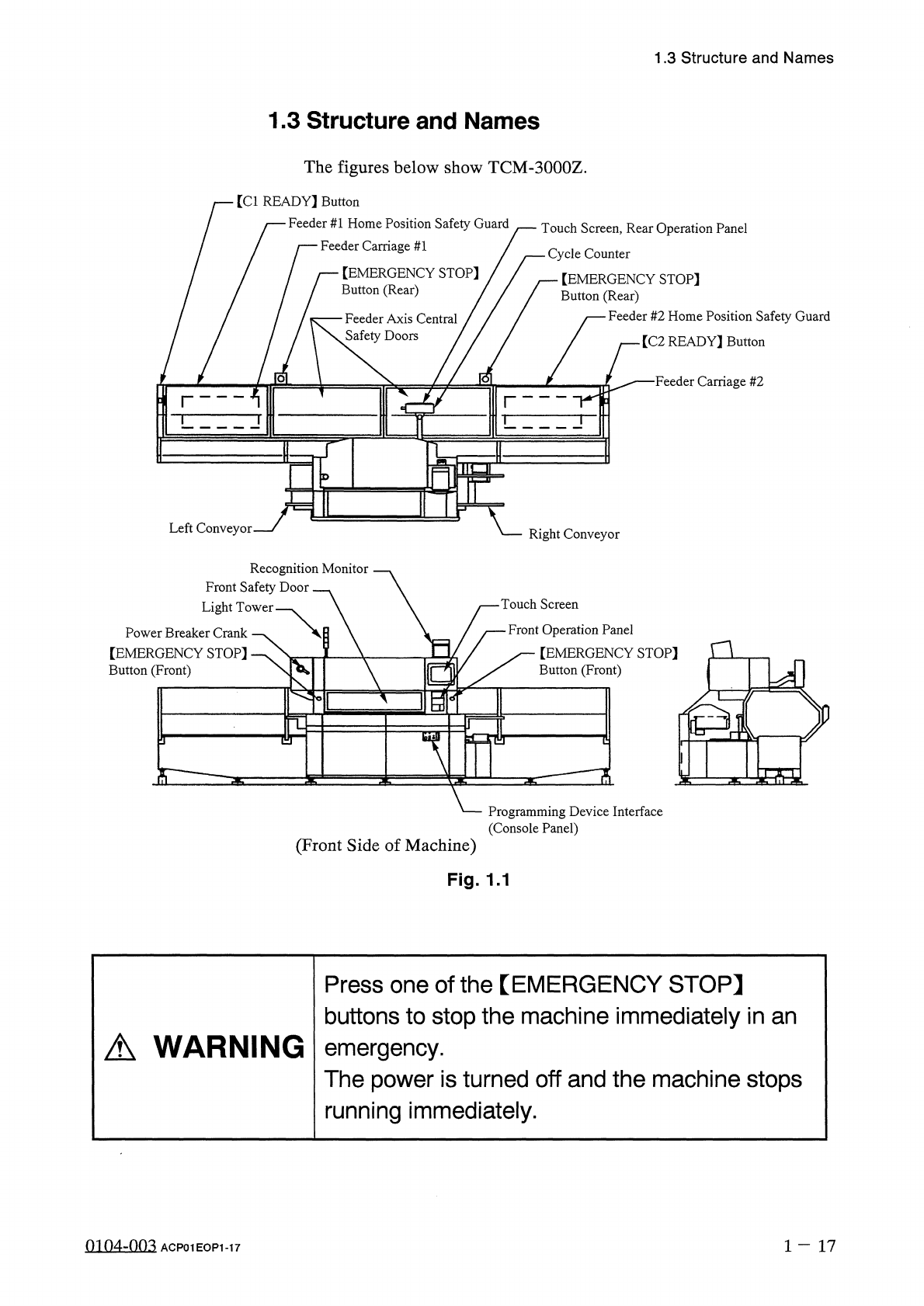
The
figures
below
show
TCM
-
3000
Z
.
[
Cl
READY
】
Button
Feeder
#
1
Home
Position
Safety
Guard
Feeder
Carriage
#
1
/
Touch
Screen
,
Rear
Operation
Panel
一
Cycle
Counter
【
EMERGENCY
STOP
]
Button
(
Rear
)
【
EMERGENCY
STOP
]
Button
(
Rear
)
Feeder
#
2
Home
Position
Safety
Guard
Feeder
Axis
Central
Safety
Doors
/
[
C
2
READY
]
Button
■
Feeder
Carriage
#
2
o
Left
Conveyor
Right
Conveyor
Recognition
Monitor
Front
Safety
Door
Light
Tower
Touch
Screen
Front
Operation
Panel
[
EMERGENCY
STOP
]
Button
(
Front
)
Power
Breaker
Crank
【
EMERGENCY
STOP
]
Button
(
Front
)
n
a
%
-
^
?
i
S
:
Programming
Device
Interface
(
Console
Panel
)
(
Front
Side
of
Machine
)
Fig
.
1.1
Press
one
of
the
【
EMERGENCY
STOP
】
buttons
to
stop
the
machine
immediately
in
an
emergency
.
The
power
is
turned
off
and
the
machine
stops
running
immediately
.
A
WARNING
0104
-
003
1
-
17
ACP
01
EOP
1
-
17