1OPERATION_.pdf - 第108页
2.6 Program Change 2.6 . 2 Adjustment of X / Y Table Section Attach and adjust the positioning pin , the positioning lever , and the movable chute according to the P . C . B . size . Turn off power to the machine before …
Wmg
Bolt
Feed
Rod
3
)
Transfer
Claw
®
I
®
P
.
C
.
B
.
cm
:
L
T
L
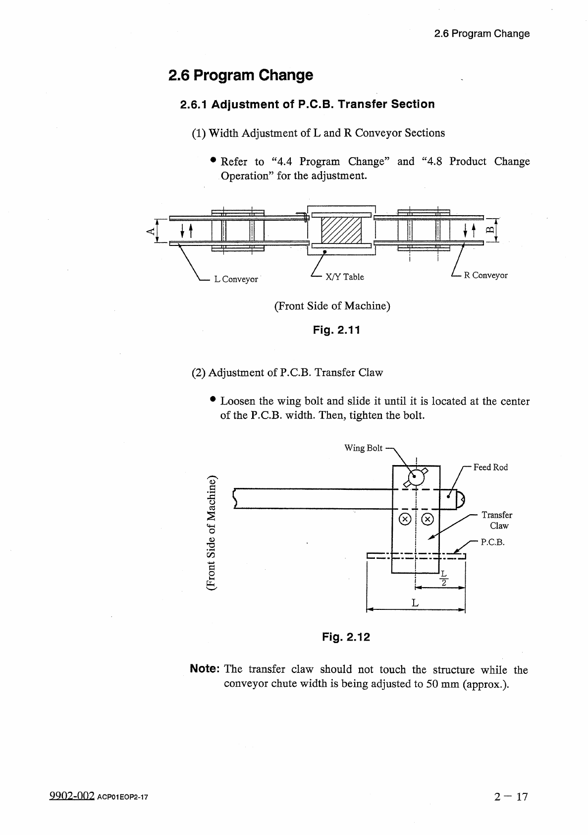
Fig
.
2.12
Note
:
The
transfer
claw
should
not
touch
the
structure
while
the
conveyor
chute
width
is
being
adjusted
to
50
mm
(
approx
.
)
.
9902
^
002
2
-
17
ACP
01
EOP
2
-
17
2.6
Program
Change
2.6
Program
Change
2.6
.
1
Adjustment
of
P
.
C
.
B
.
Transfer
Section
(
1
)
Width
Adjustment
of
L
and
R
Conveyor
Sections
•
Refer
to
“
4.4
Program
Change
”
and
“
4.8
Product
Change
Operation
”
for
the
adjustment
.
•
<
"
■
)
11
ilp
-
H
I
'
111
'
ili
—
I
鸟
「
H
H
PQ
1
1
R
Conveyor
X
/
Y
Table
L
Conveyor
(
Front
Side
of
Machine
)
Fig
.
2.11
(
2
)
Adjustment
of
P
.
C
.
B
.
Transfer
Claw
•
Loosen
the
wing
bolt
and
slide
it
until
it
is
located
at
the
center
of
the
P
.
C
.
B
.
width
.
Then
,
tighten
the
bolt
.
0
.
SIPBSJO
3
PW
}
U
0
£
)
2.6
Program
Change
2.6
.
2
Adjustment
of
X
/
Y
Table
Section
Attach
and
adjust
the
positioning
pin
,
the
positioning
lever
,
and
the
movable
chute
according
to
the
P
.
C
.
B
.
size
.
Turn
off
power
to
the
machine
before
A
CAUTION
adjustment
to
protect
your
hands
from
moving
mechanisms
.
Two
types
of
P
.
C
.
B
.
positioning
methods
“
Outline
Reference
”
and
“
Hole
Reference
”
are
provided
.
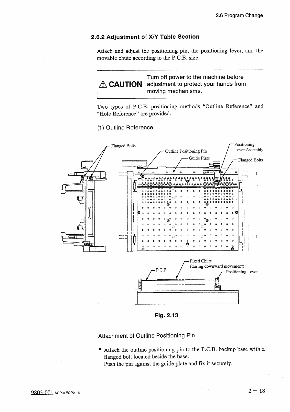
(
1
)
Outline
Reference
Positioning
Lever
Assembly
Flanged
Bolts
Outline
Positioning
Pin
Guide
Plate
Flanged
Bolts
匚
:
:
二
:
]
J
sro
0
c
0
o
0
o
0
o
0
o
00
°
o
0
o
000
°
o
°
°
o
°
°
o
|
o
00000
o
°
°
o
0
e
°
o
0
o
!
o
。
欢
。
m
双极
。
八
。
-
°
-
o
-
o
-
or
,
o
o
o
)
0
0 0
0
=
ET
O O O O O O O O O O
O n O
O
O
O
O n
o
o o o o o o o o o o
o o o o o o o o o o o
^
1
^
o o o o o o o o o o o
•
°
°
000000000
0
0 0 0
0 0
^
0
o
o
O
0
o
o
0
O
0
O
O
O
°
°
°
0
°
°
0
4
O
O
O
0
。
0
o
o
o
5
zd
°
°
°
o
°
0 0 0
°
o
°
°
°
o o o o o
o
o o o o o
o o o o o
o
o o o o o
匚二口
g
0
°
0
o
o
©
Fixed
Chute
(
during
downward
movement
)
Positioning
Lever
P
.
C
.
B
.
Fig
.
2.13
Attachment
of
Outline
Positioning
Pin
•
Attach
the
outline
positioning
pin
to
the
P
.
C
.
B
.
backup
base
with
a
flanged
bolt
located
beside
the
base
.
Push
the
pin
against
the
guide
plate
and
fix
it
securely
.
2
-
18
QRO
^
-
Ofn
ACP
01
EOP
2
-
18
2.6
Program
Change
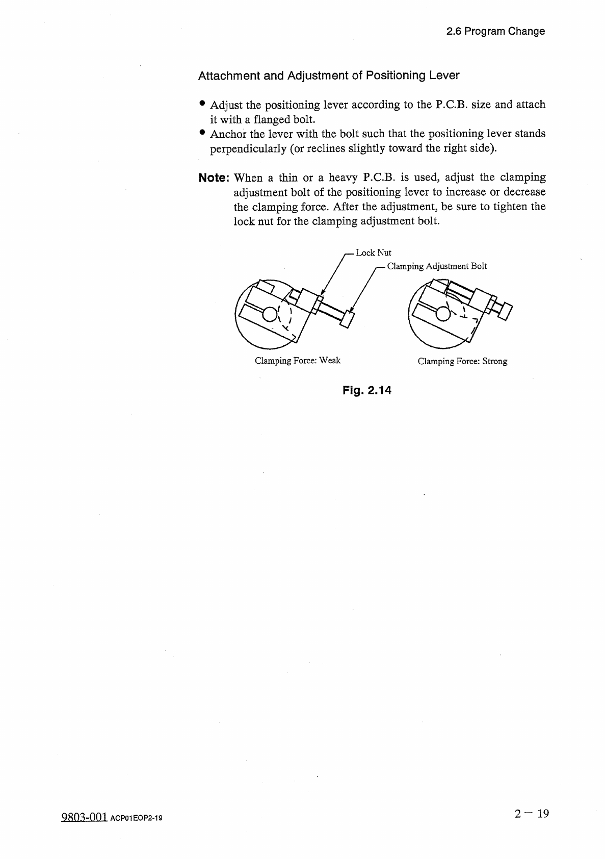
Attachment
and
Adjustment
of
Positioning
Lever
•
Adjust
the
positioning
lever
according
to
the
P
.
C
.
B
.
size
and
attach
it
with
a
flanged
bolt
.
•
Anchor
the
lever
with
the
bolt
such
that
the
positioning
lever
stands
perpendicularly
(
or
reclines
slightly
toward
the
right
side
)
.
Note
:
When
a
thin
or
a
heavy
P
.
C
.
B
.
is
used
,
adjust
the
clamping
adjustment
bolt
of
the
positioning
lever
to
increase
or
decrease
the
clamping
force
.
After
the
adjustment
,
be
sure
to
tighten
the
lock
nut
for
the
clamping
adjustment
bolt
.
Fig
.
2.14
2
-
19
9803
-
001
ACP
01
EOP
2
-
19