1OPERATION_.pdf - 第49页
1.2 Specifications ( 1 ) Shape of Vacuum Nozzle When components are to be placed close to the previously - placed components or the obstacles , vacuum nozzle shape should be considered . Refer to the “ List of Nozzle Typ…
1.2
Specifications
Approx
.
40
H
/
minute
(
ANR
)
34
.
Air
Consump
-
tion
35
.
Vacuum
Pressure
-
93
kPa
(
700
mmHg
)
Temperature
:
20
士
:
10
°
C
Humidity
:
30
%
80
%
(
Avoid
dew
condensation
)
36
.
Environmental
Conditions
6
,
000
(
width
)
X
1
,
794
(
depth
)
X
1
,
700
(
height
)
mm
(
2
,
100
mm
:
Including
the
light
tower
)
3.700
(
width
)
X
l
,
810
(
deptti
)
X
1.700
(
height
)
mm
(
2
,
100
mm
:
Including
the
light
tower
)
37
.
Basic
Dimensions
Approx
.
3
,
500
kg
(
Excluding
the
tape
feeder
and
the
scrap
box
)
Approx
.
3
,
300
kg
(
Excluding
the
tape
feeder
and
the
scrap
box
)
38
.
Mass
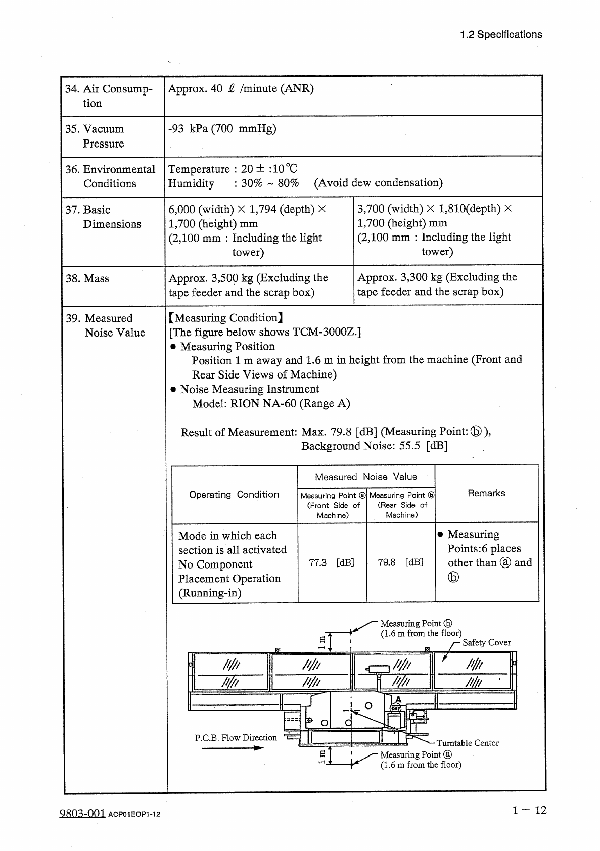
【
Measuring
Condition
]
[
The
figure
below
shows
TCM
-
3000
Z
.
]
•
Measuring
Position
Position
1
m
away
and
1.6
m
in
height
from
the
machine
(
Front
and
Rear
Side
Views
of
Machine
)
•
Noise
Measuring
Instrument
Model
:
RION
NA
-
60
(
Range
A
)
39
.
Measured
Noise
Value
Result
of
Measurement
:
Max
.
79.8
[
dB
]
(
Measuring
Point
:
⑤
)
,
Background
Noise
:
55.5
[
dB
]
Measured
Noise
Value
Remarks
Operating
Condition
Measuring
Point
®
(
Front
Side
o
-
f
Machine
)
Measuring
Point
®
(
Rear
Side
of
Machine
)
•
Measuring
Points
:
6
places
other
than
③
and
Mode
in
which
each
section
is
all
activated
No
Component
Placement
Operation
(
Running
-
in
)
77.3
[
dB
]
79.8
[
dB
]
⑤
Measuring
Point
⑤
(
1.6
m
from
the
floor
)
曰
厂
Safety
Cov
麟
麟
mu
~
W
/
/
/
in
•
I
o
崁
o
I
P
.
C
.
B
.
Flow
Direction
Turntable
Center
^
T
1
Measuring
Point
@
rn
jfc
\
jr
(
1.6
m
from
the
floor
)
1
-
1 2
9803
-
001
ACP
01
EOP
1
-
12
1.2
Specifications
(
1
)
Shape
of
Vacuum
Nozzle
When
components
are
to
be
placed
close
to
the
previously
-
placed
components
or
the
obstacles
,
vacuum
nozzle
shape
should
be
considered
.
Refer
to
the
“
List
of
Nozzle
Types
”
for
vacuum
nozzle
shapes
.
40
.
Conditions
for
Component
Placement
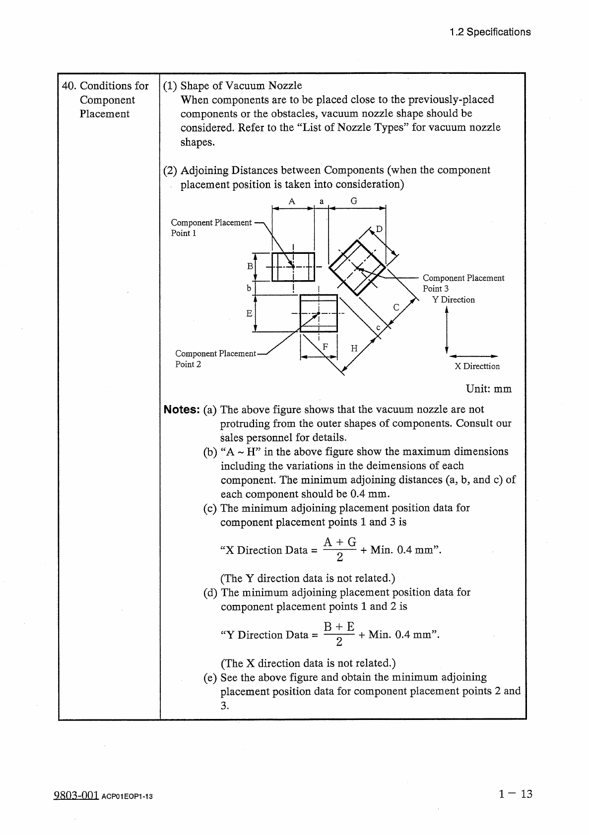
(
2
)
Adjoining
Distances
between
Components
(
when
the
component
placement
position
is
taken
into
consideration
)
G
A
a
Component
Placement
Point
1
B
"
"
Component
Placement
Point
3
Y
Direction
b
C
E
c
H
Component
Placement
*
Point
2
X
Directtion
Unit
:
mm
Notes
:
(
a
)
The
above
figure
shows
that
the
vacuum
nozzle
are
not
protruding
from
the
outer
shapes
of
components
.
Consult
our
sales
personnel
for
details
.
(
b
)
“
A
~
H
”
in
the
above
figure
show
the
maximum
dimensions
including
the
variations
in
the
deimensions
of
each
component
.
The
minimum
adjoining
distances
(
a
,
b
,
and
c
)
of
each
component
should
be
0.4
mm
.
(
c
)
The
minimum
adjoining
placement
position
data
for
component
placement
points
1
and
3
is
A
+
G
+
Min
.
0.4
mm
”
.
“
X
Direction
Data
=
2
(
The
Y
direction
data
is
not
related
.
)
(
d
)
The
minimum
adjoining
placement
position
data
for
component
placement
points
1
and
2
is
B
+
E
十
Min
,
0.4
mm
’
’
-
“
Y
Direction
Data
=
2
(
The
X
direction
data
is
not
related
.
)
(
e
)
See
the
above
figure
and
obtain
the
minimum
adjoining
placement
position
data
for
component
placement
points
2
and
3
.
1
-
13
ACP
01
EOP
1
-
13
P
.
C
.
B
.
vZ
LO
LO
P
.
C
.
B
.
(
Sectional
View
of
P
.
C
.
B
.
Positioning
Lever
)
Unit
:
mm
O
CO
■
l
>
CD
(
Top
View
of
P
.
C
.
B
.
Positioning
Lever
)
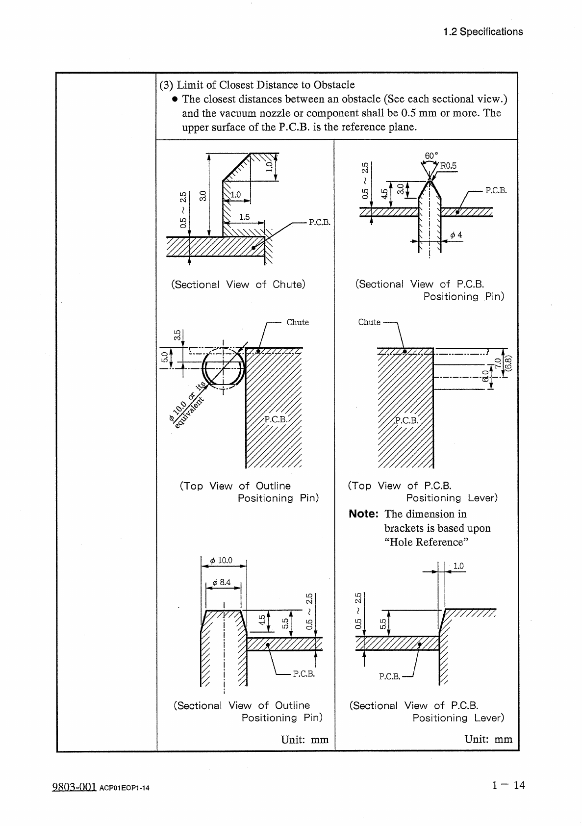
Note
:
The
dimension
in
brackets
is
based
upon
“
Hole
Reference
”
1.0
IV
7
W
77777
:
V
?
(
Sectional
View
of
P
.
C
.
B
.
Positioning
Pin
)
Chute
§
y
-
o
LO
(
Ni
1.5
LD
P
.
C
.
B
.
(
Sectional
View
of
Chute
)
Chute
uo
CO
r
:
#
(
Top
View
of
Outline
Positioning
Pin
)
10.0
J
)
8.4
ID
03
P
.
C
.
B
.
%
(
Sectional
View
of
Outline
Positioning
Pin
)
Unit
:
mm
LO
(
M
*
LO
1
—
1 4
1.2
Specifications
(
3
)
Limit
of
Closest
Distance
to
Obstacle
•
The
closest
distances
between
an
obstacle
(
See
each
sectional
view
.
)
and
the
vacuum
nozzle
or
component
shall
be
0.5
mm
or
more
.
The
upper
surface
of
the
P
.
C
.
B
.
is
the
reference
plane
.
9803
-
001
ACP
01
EOP
1
-
14
0
.
CO
9
.
寸
9
.
(
N
3
9.0