1OPERATION_.pdf - 第103页
2.4 Thorough Procedures ( from starting through ending operations including preparation ) for Automatic Operation ( Component Placement ) 2.4 Thorough Procedures ( from starting through ending operations including prepar…
2.3
Power
Supply
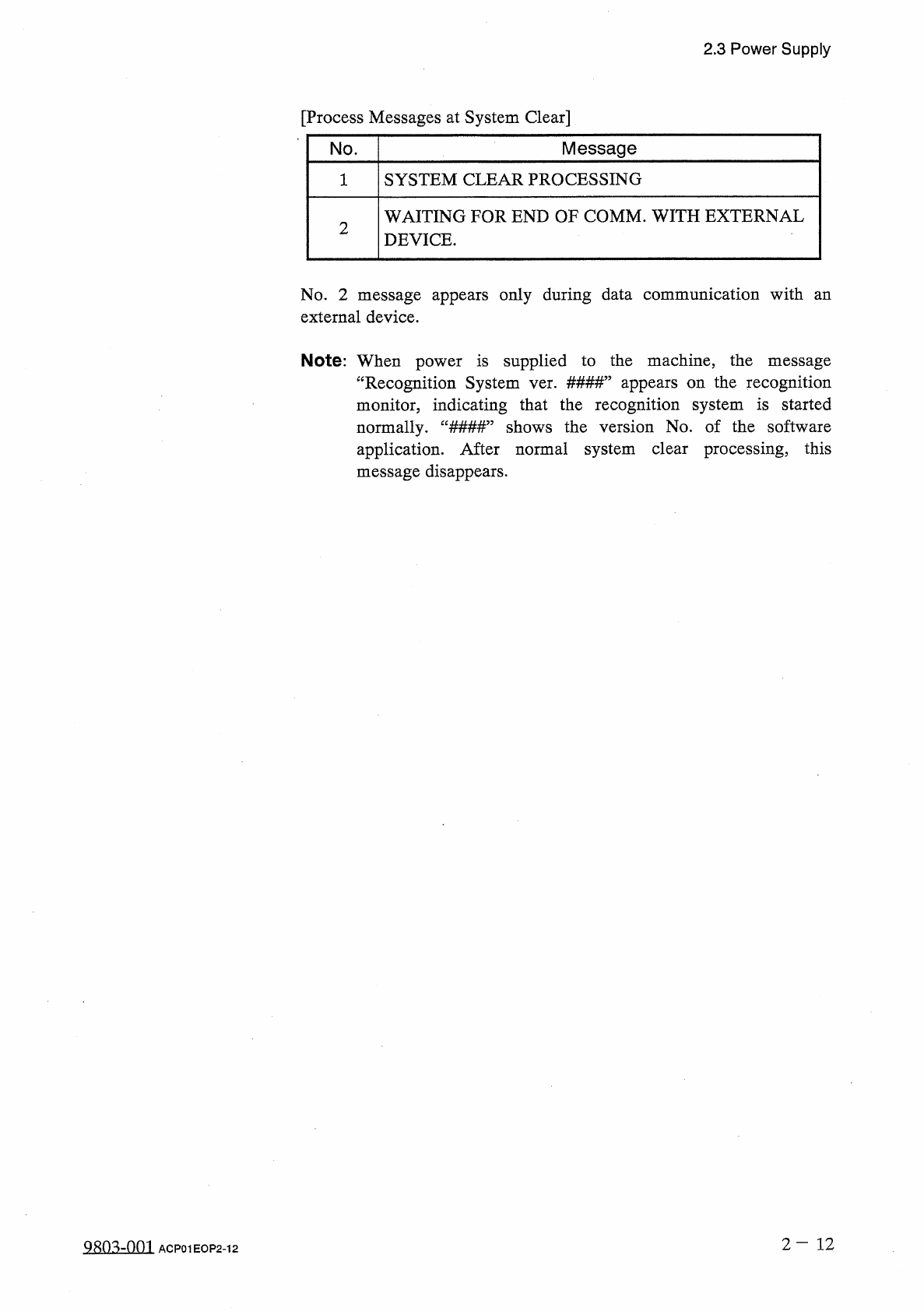
[
Process
Messages
at
System
Clear
]
Message
No
.
SYSTEM
CLEAR
PROCESSING
1
WAITING
FOR
END
OF
COMM
.
WITH
EXTERNAL
DEVICE
.
2
No
.
2
message
appears
only
during
data
communication
with
an
external
device
.
Note
:
When
power
is
supplied
to
the
machine
,
the
message
“
Recognition
System
ver
.
#
#
#
#
”
appears
on
the
recognition
monitor
,
indicating
that
the
recognition
system
is
started
normally
.
“
###
#
”
shows
the
version
No
.
of
the
software
application
.
After
normal
system
clear
processing
,
this
message
disappears
.
2
-
1 2
QRQ
^
-
001
ACP
01
EOP
2
-
12
2.4
Thorough
Procedures
(
from
starting
through
ending
operations
including
preparation
)
for
Automatic
Operation
(
Component
Placement
)
2.4
Thorough
Procedures
(
from
starting
through
ending
operations
including
preparation
)
for
Automatic
Operation
(
Component
Placement
)
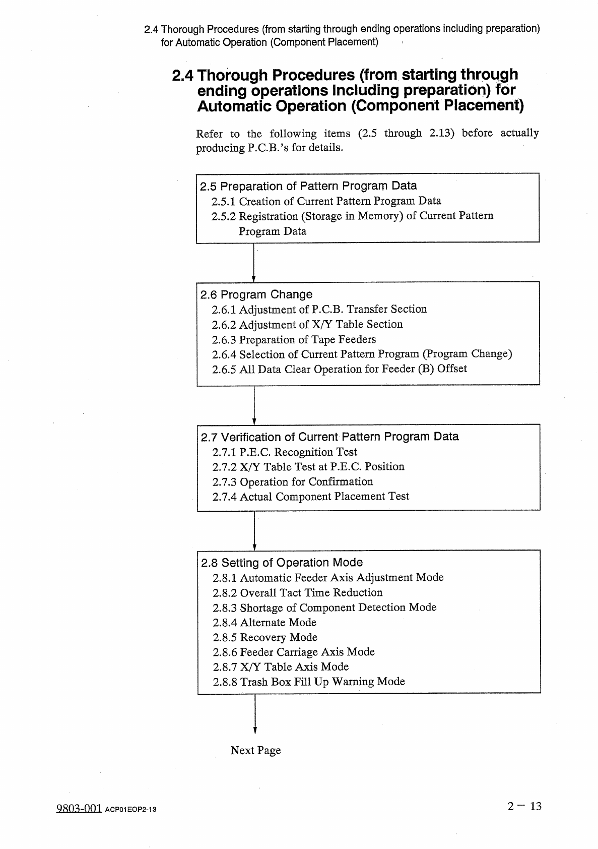
Refer
to
the
following
items
(
2.5
through
2.13
)
before
actually
producing
P
.
C
.
B
/
s
for
details
.
2.5
Preparation
of
Pattern
Program
Data
2.5
.
1
Creation
of
Current
Pattern
Program
Data
2.5
.
2
Registration
(
Storage
in
Memory
)
of
Current
Pattern
Program
Data
2.6
Program
Change
2.6
.
1
Adjustment
of
P
.
C
.
B
.
Transfer
Section
2.6
.
2
Adjustment
of
X
/
Y
Table
Section
2.6
.
3
Preparation
of
Tape
Feeders
2.6
.
4
Selection
of
Current
Pattern
Program
(
Program
Change
)
2.6
.
5
All
Data
Clear
Operation
for
Feeder
(
B
)
Offset
2.7
Verification
of
Current
Pattern
Program
Data
2.7
.
1
P
.
E
.
C
.
Recognition
Test
2.7
.
2
X
/
Y
Table
Test
at
P
.
E
.
C
.
Position
2.7
.
3
Operation
for
Confirmation
2.7
.
4
Actual
Component
Placement
Test
2.8
Setting
of
Operation
Mode
2.8
.
1
Automatic
Feeder
Axis
Adjustment
Mode
2.8
.
2
Overall
Tact
Time
Reduction
2.8
.
3
Shortage
of
Component
Detection
Mode
2.8
.
4
Alternate
Mode
2.8
.
5
Recovery
Mode
2.8
.
6
Feeder
Carriage
Axis
Mode
2.8
.
7
X
/
Y
Table
Axis
Mode
2.8
.
8
Trash
Box
Fill
Up
Warning
Mode
Next
Page
2
—
13
Qsm
-
nm
ACP
01
EOP
2
-
13
2.4
Thorough
Procedures
(
from
starting
through
ending
operations
including
preparation
)
for
Automatic
Operation
(
Component
Placement
)
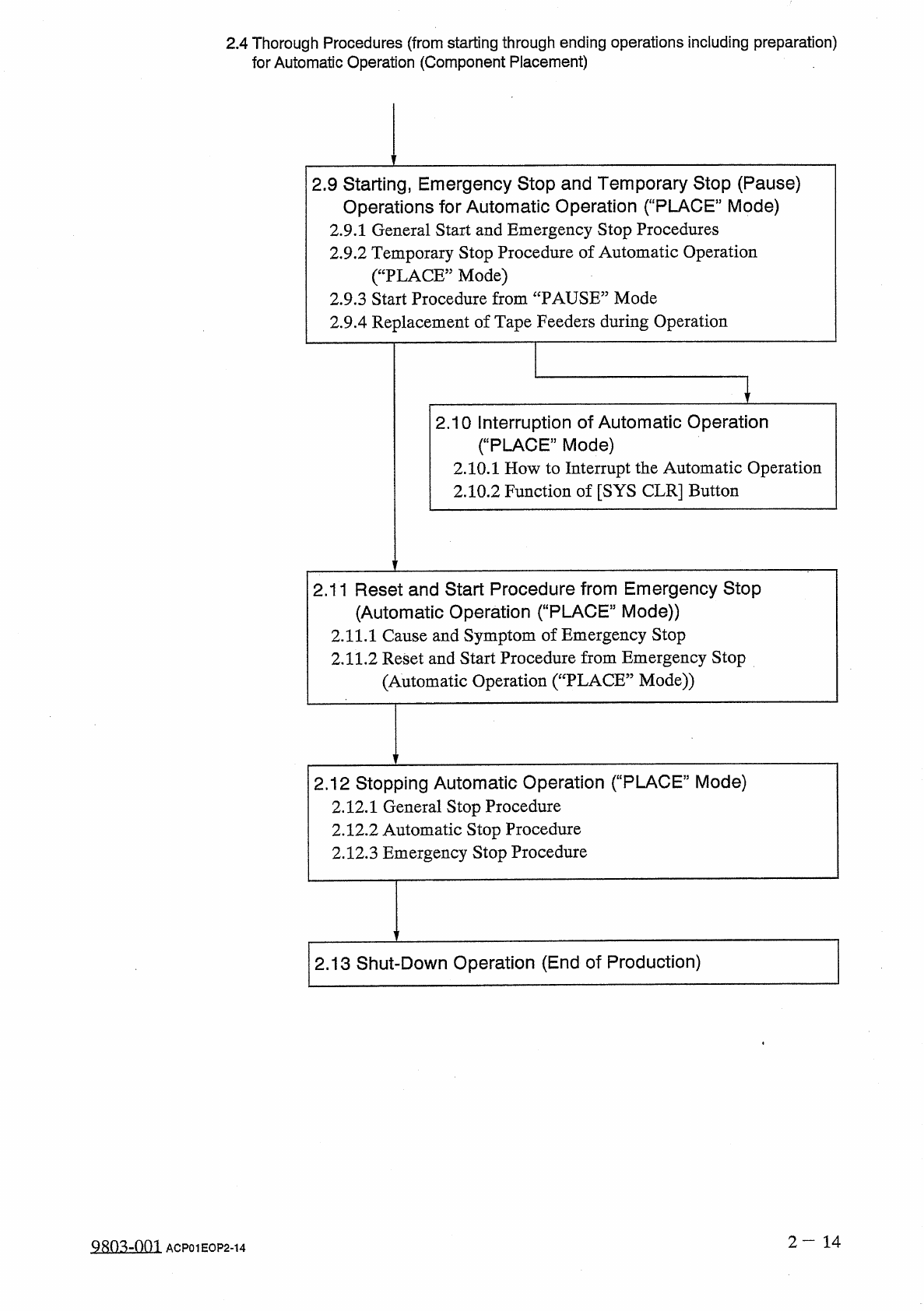
2.9
Starting
,
Emergency
Stop
and
Temporary
Stop
(
Pause
)
Operations
for
Automatic
Operation
(
"
PLACE
"
Mode
)
2.9
.
1
General
Start
and
Emergency
Stop
Procedures
2.9
.
2
Temporary
Stop
Procedure
of
Automatic
Operation
(
“
PLACE
”
Mode
)
2.9
.
3
Start
Procedure
from
“
PAUSE
”
Mode
2.9
.
4
Replacement
of
Tape
Feeders
during
Operation
2.10
Interruption
of
Automatic
Operation
(
“
PLACE
”
Mode
)
2.10
.
1
How
to
Interrupt
the
Automatic
Operation
2.10
.
2
Function
of
[
SYS
CLR
]
Button
2.11
Reset
and
Start
Procedure
from
Emergency
Stop
(
Automatic
Operation
(
“
PLACE
”
Mode
)
)
2.11
.
1
Cause
and
Symptom
of
Emergency
Stop
2.11
.
2
Reset
and
Start
Procedure
from
Emergency
Stop
(
Automatic
Operation
(
“
PLACE
”
Mode
)
)
2.12
St
叩
ping
Automatic
Operation
(
"
PLACE
"
Mode
)
2.12
.
1
General
Stop
Procedure
2.12
.
2
Automatic
Stop
Procedure
2.12
.
3
Emergency
Stop
Procedure
2.13
Shut
-
Down
Operation
(
End
of
Production
)
2
-
14
9803
-
001
ACP
01
EOP
2
-
14