1OPERATION_.pdf - 第205页
4.6 Operation Mode ② [ COMP . PLACEMENT WARNING ] DISABLE ” in the data box . Set “ ENABLE : or ENABLE : W h e n an error such as disengaged latch of a feeder occurs or the cause of such an error is removed , the machine…
4.6
Operation
Mode
4.6
.
5
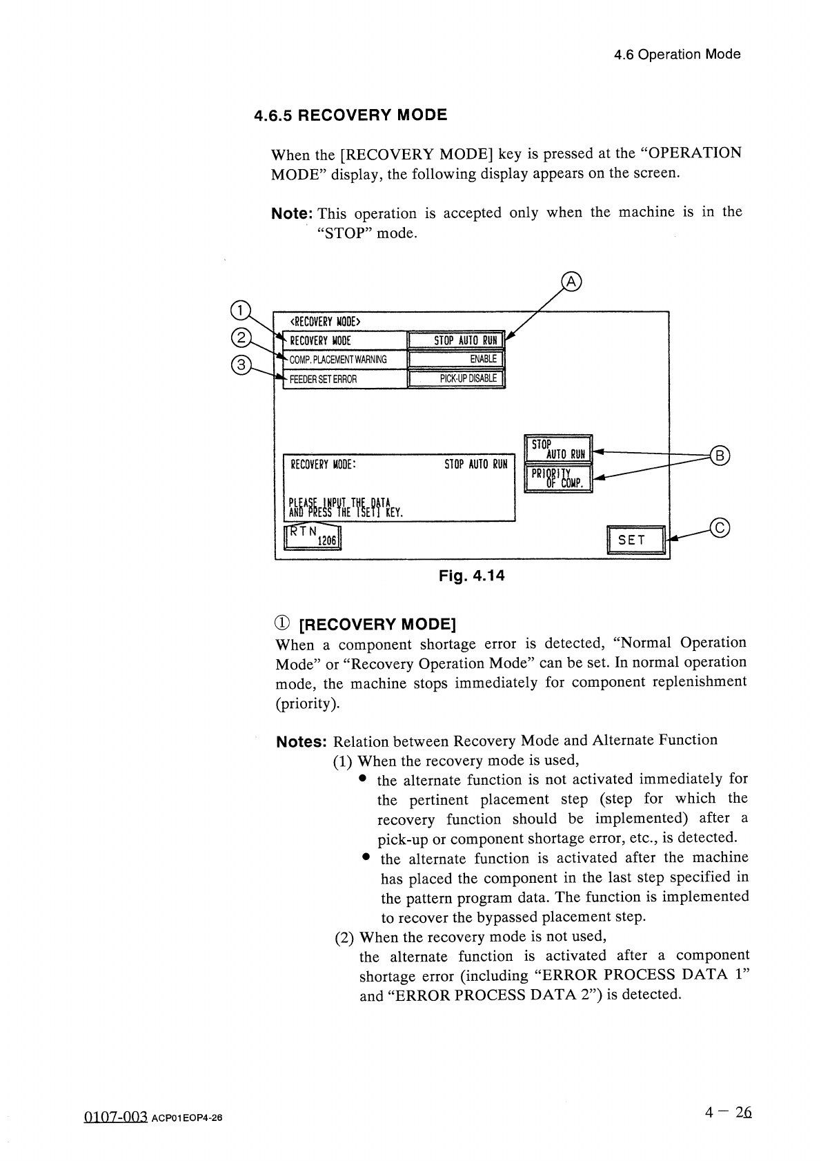
RECOVERY
MODE
When
the
[
RECOVERY
MODE
]
key
is
pressed
at
the
“
OPERATION
MODE
”
display
,
the
following
display
appears
on
the
screen
.
Note
:
This
operation
is
accepted
only
when
the
machine
is
in
the
“
STOP
”
mode
.
〈
RECOVERY
MODE
〉
RECOVERY
MODE
STOP
AUTO
RUN
ENABLE
COMP
.
PLACEMENT
WARNING
PICK
-
UP
DISABLE
FEEDER
SET
ERROR
STOP
AUTO
RUN
RECOVERY
MODE
:
STOP
AUTO
RUN
pR
,
r
&
.
Y
.
SET
Fig
.
4.14
①
[
RECOVERY
MODE
]
When
a
component
shortage
Mode
”
or
“
Recovery
Operation
Mode
”
can
be
set
.
In
normal
operation
mode
,
the
machine
stops
immediately
for
component
replenishment
(
priority
)
.
is
detected
,
“
Normal
Operation
error
Notes
:
Relation
between
Recovery
Mode
and
Alternate
Function
(
1
)
When
the
recovery
mode
is
used
,
•
the
alternate
function
is
not
activated
immediately
for
the
pertinent
placement
step
(
step
for
which
the
recovery
function
should
be
implemented
)
after
pick
-
up
or
component
shortage
error
,
etc
.
,
is
detected
.
•
the
alternate
function
is
activated
after
the
machine
has
placed
the
component
in
the
last
step
specified
in
the
pattern
program
data
.
The
function
is
implemented
to
recover
the
bypassed
placement
step
.
(
2
)
When
the
recovery
mode
is
not
used
,
the
alternate
function
is
activated
after
a
component
shortage
error
(
including
and
“
ERROR
PROCESS
DATA
2
”
)
is
detected
.
a
“
ERROR
PROCESS
DATA
1
”
4
-
26
0107
-
003
ACP
01
EOP
4
-
26
4.6
Operation
Mode
②
[
COMP
.
PLACEMENT
WARNING
]
DISABLE
”
in
the
data
box
.
Set
“
ENABLE
:
or
ENABLE
:
When
an
error
such
as
disengaged
latch
of
a
feeder
occurs
or
the
cause
of
such
an
error
is
removed
,
the
machine
completes
the
production
of
one
P
.
C
.
B
.
,
an
error
message
is
issued
,
and
the
machine
stops
running
.
Error
Message
:
“
Component
Placement
:
There
is
a
possibility
of
a
miss
mount
.
Check
P
.
C
.
B
.
on
XY
_
Table
”
DISABLE
:
When
an
error
such
as
disengaged
latch
of
a
feeder
occurs
or
the
cause
of
such
an
error
is
removed
,
the
machine
does
not
stop
running
.
Operation
•
Select
the
data
key
@
.
•
Press
one
of
the
option
keys
⑬
and
then
the
[
SET
]
key
©
.
③
[
FEEDER
SET
ERROR
]
When
a
feeder
installation
error
occurs
after
a
component
is
picked
up
at
Station
#
2
,
it
can
be
determined
whether
or
not
the
component
should
be
discarded
.
PICK
-
UP
DISABLE
:
The
picked
component
is
not
discarded
.
PICK
-
UP
ENABLE
:
The
picked
component
is
discarded
.
This
component
is
regarded
as
an
object
one
for
the
automatic
recovery
function
.
4
—
26
-
1
0107
-
002
ACP
01
EOP
4
-
26
-
1
4.6
Operation
Mode
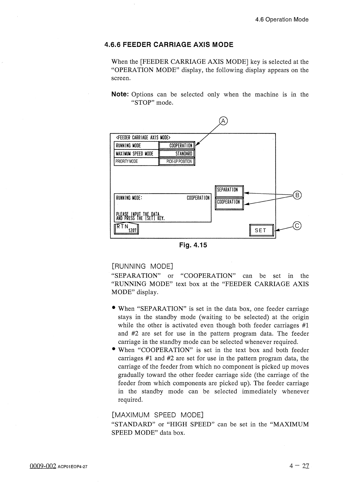
4.6
.
6
FEEDER
CARRIAGE
AXIS
MODE
When
the
[
FEEDER
CARRIAGE
AXIS
MODE
]
key
is
selected
at
the
“
OPERATION
MODE
”
display
,
the
following
display
appears
on
the
screen
.
Note
:
Options
“
STOP
”
mode
.
be
selected
only
when
the
machine
is
in
the
can
〈
FEEDER
CARRIAGE
AXIS
MODE
〉
RUNNING
MODE
COOPERATION
MAXIMUM
SPEED
MODE
STANDARD
PRIORITY
MODE
PICK
-
UP
POSITION
SEPARATION
RUNNING
MODE
:
COOPERATION
COOPERATION
齜
i
邊
wytv
mN
120
?
!
SET
Fig
.
4.15
[
RUNNING
MODE
]
“
SEPARATION
”
“
RUNNING
MODE
”
text
box
at
the
“
FEEDER
CARRIAGE
AXIS
MODE
”
display
.
cc
COOPERATION
”
can
be
set
in
the
or
•
When
“
SEPARATION
”
is
set
in
the
data
box
,
one
feeder
carriage
stays
in
the
standby
mode
(
waiting
to
be
selected
)
at
the
origin
while
the
other
is
activated
even
though
both
feeder
carriages
#
1
and
#
2
are
set
for
use
in
the
pattern
program
data
.
The
feeder
carriage
in
the
standby
mode
can
be
selected
whenever
required
.
•
When
“
COOPERATION
”
is
set
in
the
text
box
and
both
feeder
carriages
#
1
and
#
2
are
set
for
use
in
the
pattern
program
data
,
the
carriage
of
the
feeder
from
which
no
component
is
picked
up
moves
gradually
toward
the
other
feeder
carriage
side
(
the
carriage
of
the
feeder
from
which
components
are
picked
up
)
.
The
feeder
carriage
in
the
standby
mode
required
.
be
selected
immediately
whenever
can
[
MAXIMUM
SPEED
MODE
]
“
STANDARD
”
or
“
HIGH
SPEED
”
can
be
set
in
the
“
MAXIMUM
SPEED
MODE
”
data
box
.
nno
9
-
nn
2
4
-
21
ACP
01
EOP
4
-
27