1OPERATION_.pdf - 第203页
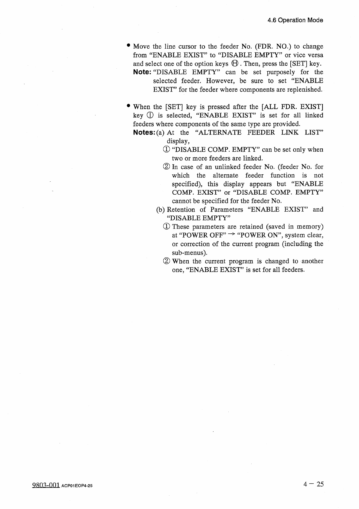
4.6 Operation Mode • Move the line cursor to the feeder No . ( FDR . NO . ) to change from “ ENABLE EXIST ” to “ DISABLE EMPTY ” or vice versa and select one of the option keys © . Then , press the [ SET ] key . Note : “…
4.6
Operation
Mode
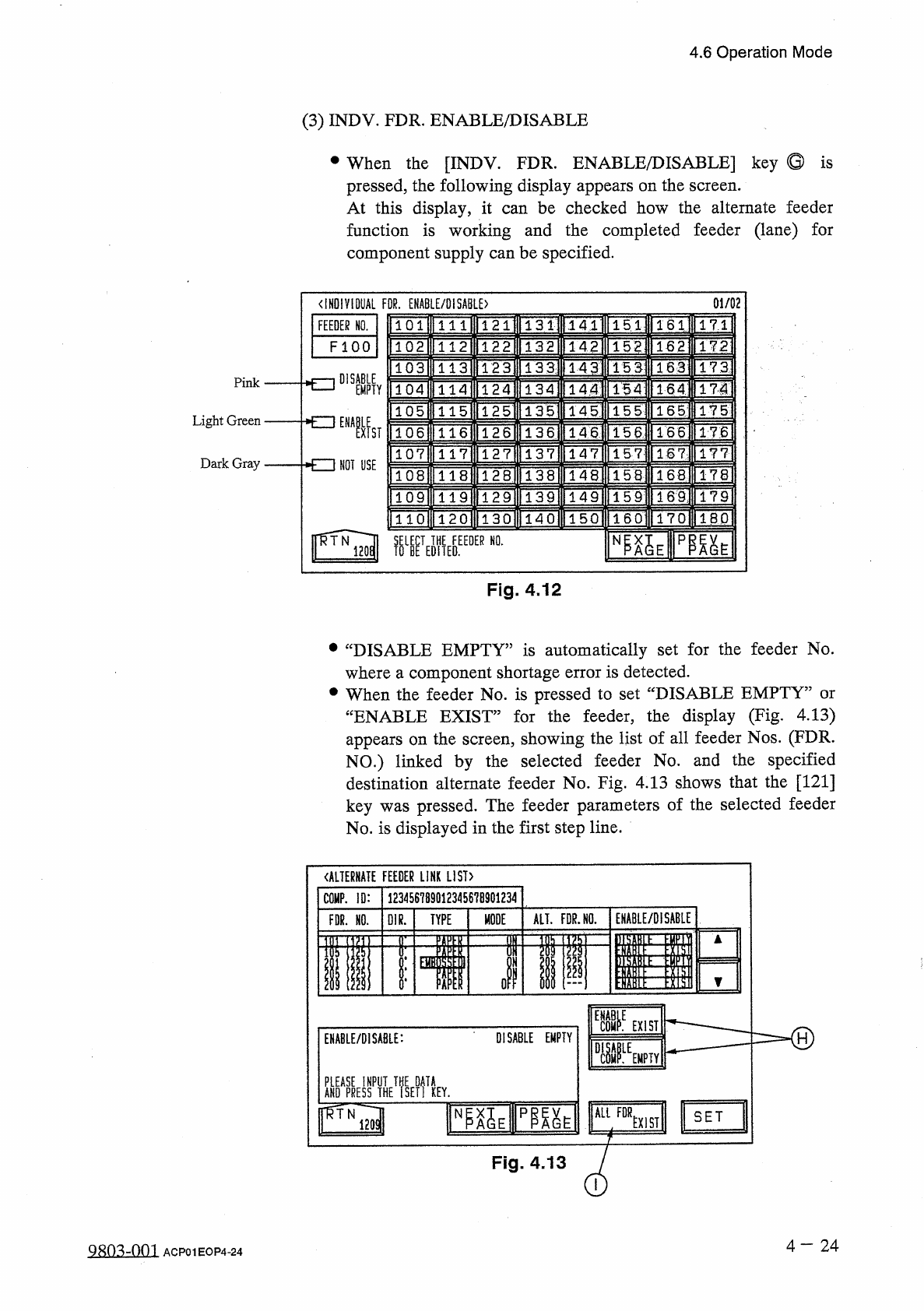
(
3
)
INDV
.
FDR
.
ENABLE
/
DISABLE
•
When
the
[
INDV
.
FDR
.
ENABLE
/
DISABLE
]
key
Q
is
pressed
,
the
following
display
appears
on
the
screen
.
At
this
display
,
it
function
is
working
and
the
completed
feeder
(
lane
)
for
component
supply
can
be
specified
.
can
be
checked
how
the
alternate
feeder
01
/
02
<
IHD
!
V
10
UAL
FOR
.
ENABLE
/
DISABLE
)
131
|
FEEDER
NO
.
151
171
141
1611
111
F l O O
132
142
152
162
172
1 12
133
]
HU
173
15
3
113
143
DISABLE
Pink
TSAI
TlH
171
144
154
EMPTY
114
1351
145
IFg
]
15
5
115
Light
Green
NOT
USE
136
llT
4
l
"
1661
TT
6
15
6
116
ns
147
117
157
177
Dark
Gray
1681
178
118
156
lWi
ITM
1
TFs
]
IT
?
159
119
T
4
~
0
lT
50
l
ITTol
1
~
6
CI
1701
IBP
1 2 0
NI
^
E
pm
^
Fig
.
4.12
•
“
DISABLE
EMPTY
”
is
automatically
set
for
the
feeder
No
.
where
a
component
shortage
error
is
detected
.
•
When
the
feeder
No
.
is
pressed
to
set
“
DISABLE
EMPTY
”
or
“
ENABLE
EXIST
”
for
the
feeder
,
the
display
(
Fig
.
4.13
)
appears
on
the
screen
,
showing
the
list
of
all
feeder
Nos
.
(
FDR
.
NO
.
)
linked
by
the
selected
feeder
No
.
and
the
specified
destination
alternate
feeder
No
.
Fig
.
4.13
shows
that
the
[
121
]
key
was
pressed
.
The
feeder
parameters
of
the
selected
feeder
No
.
is
displayed
in
the
first
step
line
.
《
ALTERNATE
FEEDER
LINK
LIST
)
123456789
Q
12345678901234
COMP
.
ID
:
ENABLE
/
DISABLE
ALT
.
FDR
.
HO
.
MODE
FDR
.
HO
.
01
R
.
TYPE
«
II
ill
ol
ii
i
]
E
11111
=
=
=
=
=
=
-
®
EXIST
DISABLE
EMPTY
ENABLE
/
DISABLE
:
fSE
?
f
!
KEY
.
ALL
FOR
NP
^
E
pm
^
SET
EXIST
Fig
.
4.13
4
-
24
QRO
^
-
Om
ACP
01
EOP
4
-
24
4.6
Operation
Mode
•
Move
the
line
cursor
to
the
feeder
No
.
(
FDR
.
NO
.
)
to
change
from
“
ENABLE
EXIST
”
to
“
DISABLE
EMPTY
”
or
vice
versa
and
select
one
of
the
option
keys
©
.
Then
,
press
the
[
SET
]
key
.
Note
:
“
DISABLE
EMPTY
5
be
set
purposely
for
the
to
set
“
ENABLE
can
selected
feeder
.
However
,
be
EXIST
”
for
the
feeder
where
components
are
replenished
.
sure
•
When
the
[
SET
]
key
is
pressed
after
the
[
ALL
FDR
.
EXIST
]
key
①
is
selected
,
“
ENABLE
EXIST
”
is
set
for
all
linked
feeders
where
components
of
the
same
type
are
provided
.
Notes
:
(
a
)
At
the
display
,
①
“
DISABLE
COMP
.
EMPTY
”
can
be
set
only
when
two
or
more
feeders
are
linked
.
②
In
case
of
an
unlinked
feeder
No
.
(
feeder
No
.
for
which
the
alternate
feeder
function
is
not
specified
)
,
this
display
appears
but
“
ENABLE
COMP
.
EXIST
”
or
“
DISABLE
COMP
.
EMPTY
”
“
ALTERNATE
FEEDER
LINK
LIST
”
cannot
be
specified
for
the
feeder
No
.
(
b
)
Retention
of
Parameters
“
ENABLE
EXIST
”
and
“
DISABLE
EMPTY
5
①
These
parameters
at
“
POWER
OFF
5
retained
(
saved
in
memory
)
TOWER
ON
,
,
,
system
clear
,
or
correction
of
the
current
program
(
including
the
sub
-
menus
)
.
②
When
the
current
program
is
changed
to
another
ENABLE
EXIST
”
is
set
for
all
feeders
.
are
one
,
4
一
25
g
^
-
nm
ACP
01
EOP
4
-
25
4.6
Operation
Mode
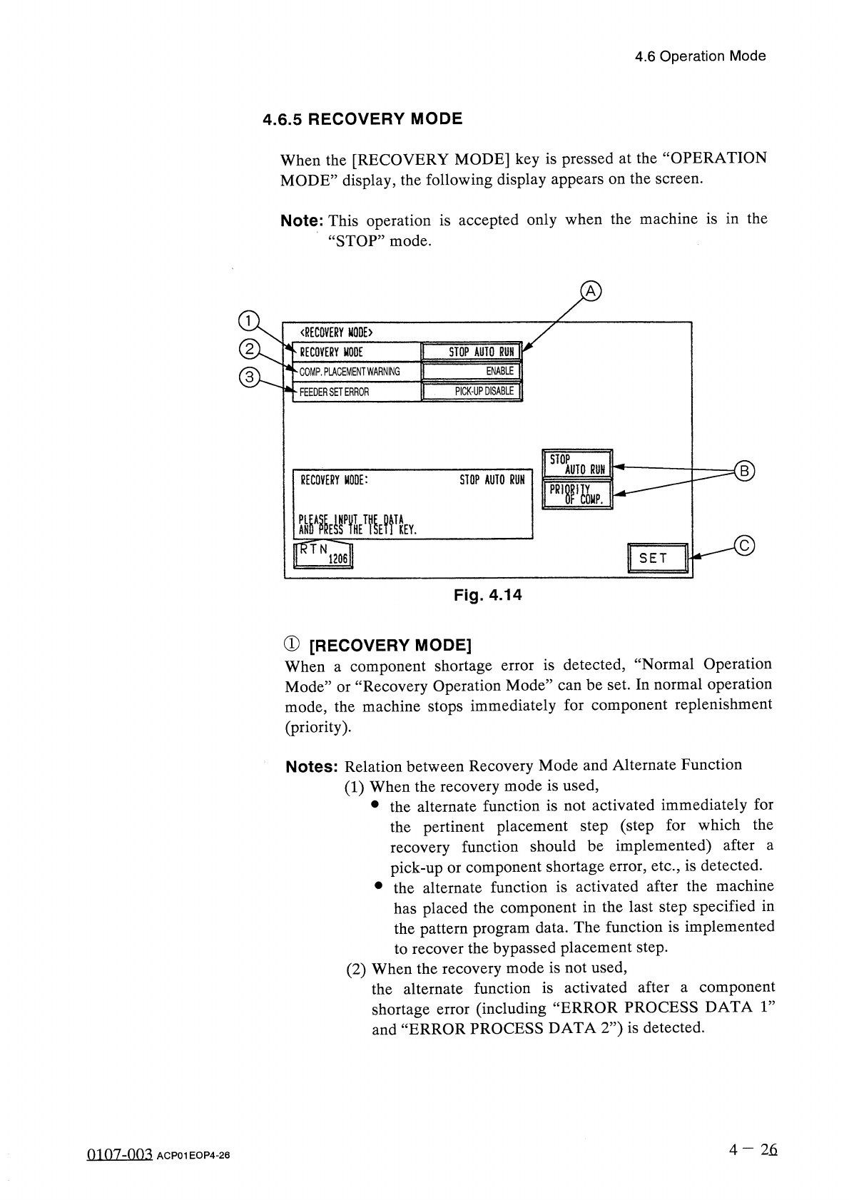
4.6
.
5
RECOVERY
MODE
When
the
[
RECOVERY
MODE
]
key
is
pressed
at
the
“
OPERATION
MODE
”
display
,
the
following
display
appears
on
the
screen
.
Note
:
This
operation
is
accepted
only
when
the
machine
is
in
the
“
STOP
”
mode
.
〈
RECOVERY
MODE
〉
RECOVERY
MODE
STOP
AUTO
RUN
ENABLE
COMP
.
PLACEMENT
WARNING
PICK
-
UP
DISABLE
FEEDER
SET
ERROR
STOP
AUTO
RUN
RECOVERY
MODE
:
STOP
AUTO
RUN
pR
,
r
&
.
Y
.
SET
Fig
.
4.14
①
[
RECOVERY
MODE
]
When
a
component
shortage
Mode
”
or
“
Recovery
Operation
Mode
”
can
be
set
.
In
normal
operation
mode
,
the
machine
stops
immediately
for
component
replenishment
(
priority
)
.
is
detected
,
“
Normal
Operation
error
Notes
:
Relation
between
Recovery
Mode
and
Alternate
Function
(
1
)
When
the
recovery
mode
is
used
,
•
the
alternate
function
is
not
activated
immediately
for
the
pertinent
placement
step
(
step
for
which
the
recovery
function
should
be
implemented
)
after
pick
-
up
or
component
shortage
error
,
etc
.
,
is
detected
.
•
the
alternate
function
is
activated
after
the
machine
has
placed
the
component
in
the
last
step
specified
in
the
pattern
program
data
.
The
function
is
implemented
to
recover
the
bypassed
placement
step
.
(
2
)
When
the
recovery
mode
is
not
used
,
the
alternate
function
is
activated
after
a
component
shortage
error
(
including
and
“
ERROR
PROCESS
DATA
2
”
)
is
detected
.
a
“
ERROR
PROCESS
DATA
1
”
4
-
26
0107
-
003
ACP
01
EOP
4
-
26